I would always go for a two way, electromagnetic and electrostatic, shielded transformer. Otherwise, maybe you should put mu- metal around the core.I'd ignore the 360 vs 365 as power line tolerance is at least +/-5% anyway. Of bigger concern is should you replace the 5R4 with two solid state devices, as silicon diodes do not have the voltage drop associated with a vac tube rectifier. You will then likely need to add some resistance in series with each rectifier diode to bring the B+ down to what the schematic indicates, e.g. 300V on B2 when measured under load. The added resistance approximates the 5R4 so this does not adversely affect supply regulation.
FWIW With silicon rectifiers as cheap as they are you could consider moving to a full-wave bridge rectifier configuration with a 360-ish volt transformer, no longer requiring a 700+ volt center-tapped transformer.
When testing a HV transformer consider using 12V AC on the 120V primary, now things are much safer and just scale all your readings by a factor of 10. And yes, it is safe to not have a load on the transformer.
You are using an out of date browser. It may not display this or other websites correctly.
You should upgrade or use an alternative browser.
You should upgrade or use an alternative browser.
RCA BC-6B Console Project
- Thread starter tablebeast
- Start date


Help Support GroupDIY Audio Forum:
This site may earn a commission from merchant affiliate
links, including eBay, Amazon, and others.
Actually in the BC-6A there are two identical power supplies. One powers the odd numbered preamps, the other the even numbered preamps. So I'd expect the supply's isolation resistor values to change little as each supply runs less than 6 preamps.Looking at the larger BC-6A this time, there is a similar distribution but with some different values of course.
https://www.worldradiohistory.com/Archive-Catalogs/RCA/RCA-BC-6A-Console.pdf
As for figuring preamp current look at the supply outputs that feed 5 preamps. You know the voltage drop from output to output, you know the resistor values, calculate the resistor current (i=e/r) and divide by 5. One could do a rough crosscheck by making some assumptions about preamp stage idle plate voltages and then calculating plate currents, but that would not be very accurate. Another approach is to measure one preamp using an adjustable HV supply. FWIW I use a recapped Heathkit SP-2717 (aka IP-17) that works well for powering tube stages (and for reforming NOS electrolytics).
systemtruck
Well-known member
Yes I forgot about the dual supply! Thanks for the reminder.Actually in the BC-6A there are two identical power supplies. One powers the odd numbered preamps, the other the even numbered preamps. So I'd expect the supply's isolation resistor values to change little as each supply runs less than 6 preamps.
As for figuring preamp current look at the supply outputs that feed 5 preamps. You know the voltage drop from output to output, you know the resistor values, calculate the resistor current (i=e/r) and divide by 5. One could do a rough crosscheck by making some assumptions about preamp stage idle plate voltages and then calculating plate currents, but that would not be very accurate. Another approach is to measure one preamp using an adjustable HV supply. FWIW I use a recapped Heathkit SP-2717 (aka IP-17) that works well for powering tube stages (and for reforming NOS electrolytics).
So I went and dissected the cascades of power for the dual supply BC-6A, on both supply #1 and supply #2. Putting it here below in case anyone in future can use the breakdown info.
It seems that RCA was fine with strapping either 4 preamps or 5 preamps to the same filter spec/cutoff design. Since I’m designing for 8 total, I’m wondering if it makes sense to implement a new split point like they do for the B5/6 + B7/8 rails. So use the source point for the preamp RC and tack on another RC directed parallel from that, and have each leg feed 4 preamps. So from the last break off point that would be a 600R/40uF > 600R/80uF > B3 RAIL > 3900R/120uF > B4 RAIL, two times in parallel instead of just the one leg, each leg feeding 4 preamps.
The transformer i have provides above 500mA, so that shouldn’t be a limiting factor.
I’m not yet sure how to interpret the current limitations of the 5R4GY.
https://frank.pocnet.net/sheets/127/5/5R4GY.pdfThe full wave specs in datasheet say that with 2100 “max peak inverse plate voltage,” it provides 250mA DC output current. At higher ”max peak inverse plate voltages”, the current output drops below 250mA (if using a capacitor not a choke). So my question is, what is the “max peak inverse plate voltage“ for this RCA power circuit? Wondering if i can hammer out the current limit for this setup. Also wondering if it can offer double 250mA, since it uses two plates. I doubt that though!
If the tube can in fact put out 250mA, then I need to do all of the math of all pcb’s and see if perhaps the high voltages total up less than 250ma. I believe each of the four 6V6’s will chew up about 35mA at all times. That would be 140mA total. So that instantly brings down the available plate current for the rest of the pcb’s to 110mA. Maybe that’ll be enough, since i know each pcb might only use something like 6-8mA. But if it doesn’t add up, and I have all of the above correct (about the 250mA limitation of the tube), then i may need a separate supply dedicated for just those four 6V6’s.
SUPPLY #1 Filter Cascade:
*100R >>>>>>>>>>>>> **
** 750R/40uF > B2: (unused rail)
** 3000R/40uF > B1: 5AR13 CH 1 LINE AMP
** 600R/40uF > 600R/40uF > ***
*** 5600R/40uF > B8 12K/40uF > B7 : (unused rails)
*** 5600R/40uF > B6 12K/40uF > B5 : 5AR11 CH1 BOOSTER AMP (CH 1 SUB MASTER)
*** 600R/40uF > 600R/80uF > B3 > 3900R/120uF B4: 5AR1, 5AR3, 5AR5, 5AR7, 5AR9
SUPPLY #2 Filter Cascade:
*100R >>>>>>>>>>>>> **
** 750R/40uF > B2: 5AR16 PGM-TB MON AMP, 5AR15 CUE FEED MON AMP
** 3000R/40uF > B1: 5AR14 CH2 LINE AMP
** 600R/40uF > 600R/40uF > ***
*** 5600R/40uF > B8 12K/40uF > B7 : 5AR12 PGM-TB.MON PRE-BOOST
*** 5600R/40uF > B6 12K/40uF > B5 : 5AR10 CH2 BOOSTER AMP (CH 2 SUB MASTER)
*** 600R/40uF > 600R/80uF > B3 > 3900R/120uF B4: 5AR2, 5AR4, 5AR6, 5AR8
Max peak inverse voltage (PIV) for you can't be any higher than the transformer end-to-end voltage which is 2*360*sqrt(2) = 1018V, well below the 2100 the tube is rated for. (A bit higher on AC line surges, of course.) Actual PIV will be less under load as the 5R4 will drop some from plate to cathode, as much as 65V at 250mA, and more on peaks.
Per datasheet Curve 1 the 5R4 is rated for 250mA continuous plate current, but the absolute maximum ratings indicate peaks to 650mA will be tolerated. Remember that each plate has about 260 Ohms resistance (from Curve 2 showing 65V drop at 250mA), so the more current you draw the more drop from plate to cathode, and the more all your outputs sag.
Bear in mind 250mA load does not translate to 250mA plate current. The plate only conducts during AC peaks, or <50% of the input half cycle, possibly <25%. So a 250mA average could easily exceed the 650mA plate current maximum. At that current expect even more drop across the tube, although the duty cycle helps keep the power dissipation down. Another reason for using a choke input filter scheme is that it increases the duty cycle of the tube conduction, reducing the peak plate current.
Another concern is heat. The 5R4 filament takes 10W, and at 250mA plate current the plates dissipate another 16W. Being in a vacuum all that heat is primarily radiated rather than conducted. Lighting up adjacent electrolytic filter caps with all that heat does not help their life. Adding a second 5R4 might help some, but the total power dissipation/radiation will not drop because the second filament adds 10W. (Yet another reason why modern silicon rectifiers are so dang handy.)
At this point it makes a lot of sense to me why RCA used dual power supplies. I would be tempted to use your 360-0-360V 500mA transformer to feed two 5R4s, and basically duplicate the original supply design from each 5R4 cathode on out. Or dump the 5R4 filament heat and use, in each transformer hot lead, a 2A rated 1500 PIV diode with a resistor (100 Ohms 25W ?) to somewhat emulate the tube resistance. Then feed your split/duplicated filtering approach.
systemtruck
Well-known member
Thanks!!Bear in mind 250mA load does not translate to 250mA plate current. The plate only conducts during AC peaks, or <50% of the input half cycle, possibly <25%. So a 250mA average could easily exceed the 650mA plate current maximum. At that current expect even more drop across the tube, although the duty cycle helps keep the power dissipation down. Another reason for using a choke input filter scheme is that it increases the duty cycle of the tube conduction, reducing the peak plate current.
I’m still new to rectifier tube concepts so wrapping my head around how a rectifier tube works and how its limitations are reflected in designs. So as for this one bit about 250mA/650mA, are you saying that if i’m drawing lets say exactly 250mA on the HV rail using all of my modules/pcbs, that the 5R4 could potentially be exceeding its 650mA plate max and so I should limit my total current draw from the pcb’s to something well below 250mA total? Or are you saying the opposite.. that if the pcb’s are drawing a total of 250mA, that I should actually still have plenty of current headroom from the 5R4?
As for the idea of strapping two 5R4’s to the transformer… yes i have actually been trying to find a good resource for how to design that. I haven’t found many examples that show two rectifier tubes can pull from one HV transformer point.
But i did find some info stating that you’d need two separate 5V filament sources, one for each rectifier tube. That’s actually kind perfect for my transformer setup because i have a separate 5V toroidal that has two secondaries. Each secondary offers 4A. The 5R4 is spec’d as drawing 2A from 5V. I was planning to just provide all 8A to the one 5R4 because i had nothing else to do with the extra 5V secondary, but maybe I can give each 5R4 its own 5V 4Amps and that’ll set me up for a dual supply? That would be great news. Would just need to acquire another RCA 5R4GY which isn’t difficult or too costly.
So if i’m that close to a dual supply already, with my 550mA from 360-0-360, and each 5R4 offering 250mA max, then it sounds like this could be set up to offer just as much current as the RCA dual supply situation. If i can do this, then i can pretty much divvy up the pcb’s how they had it. I had thought that they used a dual supply for the purpose of on-air reliability, which is something they sorta mention in their user manual or marketing sheet that i had seen. Even if one supply goes down, you still have mutiple channels to use to stay live on the air, etc. But i makes sense that there would be electrical benefits and/or necessities behind this decision too.
I’ll need to find some schematic examples of how this is done…
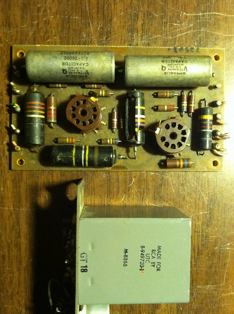
I have a feeling I wrote down current on the paper in the pic, probably under the preamp on top of it. Don't know where the paper is now.
I'd be very surprised if pre/booster current is more than 10mA and PGM current more than 40-50mA. In line with all the preceding types. Old control rooms in the pre-AC days. Etc. Altec 250SU fully loaded is something like 275V @ 275mA, and those are among the most power hungry modules anyone ever sold. Just about nothing uses 500mA. You'll have to regulate or burn off (heat) excess current capacity to get voltage down to correct levels.
I'd be very surprised if pre/booster current is more than 10mA and PGM current more than 40-50mA. In line with all the preceding types. Old control rooms in the pre-AC days. Etc. Altec 250SU fully loaded is something like 275V @ 275mA, and those are among the most power hungry modules anyone ever sold. Just about nothing uses 500mA. You'll have to regulate or burn off (heat) excess current capacity to get voltage down to correct levels.


Yes, I'm saying a 250mA total supply load could cause the 5R4 plate current to exceed the 650mA maximum rating. While a half cycle of a sine wave from the transformer is 180 degrees it is possible the rectifier conducts only during the peak 45 degrees (at 90 +/- 22.5 degrees). That would be a 25% duty cycle. to average 250mA the peak needs to be 4 times that, or 1000mA.
Yes, you should use two isolated 5V filament windings. (Ideally the windings would be center tapped, that's where you would best pull the DC output from.) Since you have two 5V filament windings use one for each of the two 5R4s you need. Just wire the high voltage transformer you have to the second 5R4 just like the first. From the filament windings out just make two identical supply systems, just like RCA did with their approach. FWIW each 5R4 takes 2A filament current, that's all they will take from each 4A winding.
Yes, the dual supply as redundant isn't true at all, but you know marketing folks...
MidnightArrakis
Well-known member
Mr. EMRR: Is it possible for you to provide the requested information asked within my request shown below?The cards are small, and have no local filter caps. Close up of the parts in question.
>>> GREETINGS!!! -- It seems to me that some members of this forum/thread may benefit from having a -- NEW/OLD -- version of this PCB available for whatever reason it is that they may need one or more. So, I thought I would design a new PCB of this card and make the GERBER files available for whomever wants to have some of these PCB's fabricated for one of their projects. However, before I can do this, I need the mechanical details of this PCB so I am able to begin.
Since you apparently have an original PCB within your possession, I am wondering if you could please be so kind as to accurately measure the various details of this PCB and provide me with the dimensions as shown within a drawing I have made. You just need to provide the measurements that correspond to the appropriate letters as shown:

A =
B =
C =
D =
E =
In addition, if you could also let me know which of the schematics that are available is a "preferred" one, along with any information that may be available as to any preferred/undocumented modifications or updates. It would also be useful with knowing the various resistor wattages and capacitor types and voltages. And, finally.....if there is anything about this PCB that is not documented and/or known about that would be useful in knowing, please share that as well. THANKS!!!
I, personally, have no interest in building this PCB. My only interest is that I am not doing anything right now as I am growing older each day and I have all of this expensive CAD-design software here on my computer just sitting idle. So, I would much rather do -- something/anything -- that may be helpful to someone else than just collecting more dust on the top of my bald head!!! THANK YOU!!!
/
systemtruck
Well-known member
@Hubbub @emrr
Alrighty understood regarding full wave current and also heat issues.
At this point I could either steer the modern direction and convert the initial power stages to modern cooler rectification, or i could just take a chance with the dual 5R4 approach and see how it turns out. The latter sounds more fun and is perhaps more authentic sounding so i’ll try that, and can always divert back to a modern design if something doesn’t go well.
As for current draw, I suppose it HAS to be under the 650mA per 5R4 limit if I distribute the modules exactly how RCA did it with their dual supplies, and match their module count. I think may actually end up with exactly the same total modules since i only have 8 preamps not 9, but I’m adding one booster preamp for the second monitor amp ( they didn’t use a booster for both their monitor amps). Since those two modules are the same schematic, I believe I’ll end up at the same total power usage as RCA.
I do see something funny about their distribution though.. which is that both of their monitor amps are on B2-2 for some reason, and B2-1 remains empty. Seems like common sense would be to put one monitor amp on B2-1 and the other on B2-2. Or, maybe it is in reality, and this schematic note is wrong. Or maybe there is some sonic/noise advantage to having both monitor amps on the same supply or rail.
I’m going to locate the power supply in a rear compartment of the console that has nothing else in it except for two VU meter guts sitting way above the supply. The interior dimensions of this dedicated rear compartment will be 20” long, 5-6” wide, and around 10” high. There will of course be air vent holes in various places. But as for attempting to distribute heat from the transformer, two 5R4’s, and power caps, what is the common sense way to hook up some heat sinks to this RCA power circuit? I might try to find more pics of the BC-6A internals to see if i can spot anything obvious.
systemtruck
Well-known member
Double post here…
Have a separate thing to solve, which is the transformers on the Program output amplifiers. Been doing a little sifting through options and am uncertain about this output transformer design, and replacing it. I”m guessing the main function is something around 4:1 or 8:1, maybe like 20/30k to 600R.
But if you look at the total schematic you can see that the primary side of 5T10 and 5T11 uses an extra primary winding for FB in the PGM output circuit. On the actual PGM out (5AR13,5AR14) schematic you can see that pin 8 (connected to pin 5 of transformer) goes back to the cathode of the first tube via a resistor. This same primary winding, if you look at the larger schematic again, also feeds a bus rail that distributes the audio elsewhere for different purposes like switchable monitoring and such. Haven’t traced it fully but I know point 65 and 67 go down to the monitor amps.
I don’t think I’ll be needing that bus rail. It’s pretty easy to find a transformer that can replace the center tapped push pull tube output ratio, but i don’t have any specs about these old transformers so don’t know how I’d find one that has that extra primary winding, and wouldn’t now what its impedance/ratio situation is. There is little to no info on these transformers.
Anybody have any thoughts about how to design without that extra primary winding? Maybe just implement the feedback circuit on its own and the extra primary winding can be ignored since its purpose is for creating that bus rail? Maybe the winding is just a buffer for the bus rail?
@emrr do you have any of these output transformers installed and know the specs of these things?
I’ve marked with red arrows the points in question…
systemtruck
Well-known member
Any sense of what the primary and secondary impedances would be, for this push pull to line output? Having trouble finding consistent info in sale listings from the past. Some state low values, some state high values.Same output transformer as the BA-23 and BA-25.
it's a 12dB step-down, assume 1dB winding loss, you can calc the turns ratio from there. The resistances pencilled in on the BA-25 scheme are my notes, also a clue. Load ballpark frequently referenced to 2x plate resistance, but can vary wildly. This isn't really a transformer you'll probably find off the shelf from anyone, so adaptation will be required.
I looked at the BC-3 power transformer I have, there's no information printed on it. I'm sure I spent $200 on it, would let go for same.
I looked at the BC-3 power transformer I have, there's no information printed on it. I'm sure I spent $200 on it, would let go for same.
systemtruck
Well-known member
Couldn’t find your notated BA-25 schematics, so thanks for the dB info about the step down! I can certainly work with that. Guessing it would be something like a 8000R > 500R transformer, center tapped on primary for the push pull. I’ll shop around, but let me know if you happen to have a pair of those output XFO’s available.it's a 12dB step-down, assume 1dB winding loss, you can calc the turns ratio from there. The resistances pencilled in on the BA-25 scheme are my notes, also a clue. Load ballpark frequently referenced to 2x plate resistance, but can vary wildly. This isn't really a transformer you'll probably find off the shelf from anyone, so adaptation will be required.
I looked at the BC-3 power transformer I have, there's no information printed on it. I'm sure I spent $200 on it, would let go for same.
So far this is the most promising looking pair i could find: Brand New Pair of UTC P-10 P-P Tube Preamp Line Output transformers 30K - 500ohm | eBay
It’s only +8dBm but that might be fun sounding to saturate.
However they are 30K on the primary. Maybe not ideal for the PP output to see 30K?
Pretty sure I’ll just end up getting a pair of new Cinemags or Lundhals or Jensens.
In any case i’ll have to design without the tertiary winding for the circuit feedback. I did a little homework and found out that it helps improve the THD to draw the feedback from the transformer’s actual real time output performance/voltages rather than just by doing some math with an internal feedback. So i think the worst case is I’ll have to live with some extra THD, which is totally fine for this project! I do wonder what the feedback resistor would be now though, and what point in the PGM schematic the FB pathway would pull from if it’s not pulling from the winding.
Thanks for the offer about the power transformer. If I’ve done the math right, I think i’ll be exceeding the current draw of the BC-3 by a few modules and don’t want to chance it.
systemtruck
Well-known member
Found it. Pasted below.UTC P-10’s….def no….this amp puts out +24 and they surely won’t handle the current. Plus the price is beyond the beyond, insanity. BA-25 - tech docs
Those hand written impedances are surprising. 375, 380, 49 on the primary, 8.8, 8.8 on the secondary? That seems kinds like a speaker output transformer where as this is for going to line out. Or maybe it’s a multi purpose type of transformer?

ruffrecords
Well-known member
More likely DCR values than impedances.
Cheers
Ian
Cheers
Ian
systemtruck
Well-known member
Ok thanks.
Still have some homework to do.
This seems to be a very crucial component to the whole build since the output transformers are going to interface with the outside world.
I’m wondering if the fact that most modern line level inputs (ie your basic audio interface) will have 10K input impedances should affect the transformer selection. I mean as opposed to whatever the most common input impedances were for line level devices in the late 1950’s.
I gather that the parallel push pull 12AU7 design has a certain total load resistance that the transformer should match well to at its primary.
If the original output transformers present a 12dB decrease, that says to me it’s a 4:1 ratio. And if it’s a 4:1 ratio, and it’s a 500/600 ohm output, then the input impedance is around 2K/2.4k.
I can’t find much data on the total load resistance of 12AU7’s in parallel push pull, so can’t determine if RCA wanted to give the circuit a bridge input or if RCA was choosing a primary that’s higher than the PPP load res or if they were choosing a primary that’s lower than the PPP load res.
If I find a transformer that’s lower input impedance than perhaps is proper for the PPP, maybe it is all compensated for by the fact that the transformer itself will see a higher load than the circuit was designed for? Like say the PPP load res is 10K or something, but I can only find a 5K primary imp transformer. If the line input impedance on modern external equipment is higher than 75 years ago, maybe the PPP 12AU7’s will actually see something good/high enough since the 5K will be raised?
ruffrecords
Well-known member
You are right that most modern sources expect to drive a 10K load although some will drive much lower loads. Back in the day everything was 600 ohms in and out.
Cheers
Ian
Cheers
Ian
systemtruck
Well-known member
Getting a little closer on narrowing in on possible transformer options. The only way to nail it will be to find an actual UTC P-1792 as pictured below, sitting in a BA-23A. Also shown below that is the BA-23A Program Amp schematic, which is strikingly similar to the Program Amp schematic for these BC-x consoles.
But working closer anyways… I dug up a couple Cinemag transformers that are almost there.
One is the CM-9600-T.
https://cinemag.biz/application_notes/PDF/AN-106.pdfIt’s 15K center tapped / 600 ohm, and has a tertiary winding for the same purpose as the original, feedback from the winding for better THD.
In that example schematic, the Ampex preamp that uses push pull to line, it’s just one set of 12AU7 triads and thus the push pull stage has, to the best of my understanding, twice the load resistance of a parallel push pull 12AU7 setup, and so the transformer being 15K is probably twice as high of a value than the RCA/UTC transformer primary. That’s my best guess.
Lastly, it’s stated max level is 6W, and I’m not sure exactly how that translates to dBm.
I think that the parallel 12AU7 PP will have half the load resistance, so if the above is correct then it would be around maybe 7.5k, which is probably the ballpark of what the transformer needs at its primary.
I also found that the famous EQP-1A uses a 12AU7 push pull to line stage. It’s got the legendary Peerless S-217-D output transformer. It just so happens that Cinemag has reproduced this transformer and still makes them.
https://cinemag.biz/output/PDF/CM-S217D.pdfInstead of 15K like the CM-9600-T, the S-217-D has 12.5K at the primary. A little lower. And this mates with the EQP-1A’s PP stage, not parallel. So again we’re talking about twice the load resistance. So if we followed suit and halved the load resistance, in concept this circuit is wanting to see 6.25K instead of the 7.5K above. Pretty similar.
This S-217-D also has a tertiary winding that could maybe be used for the THD benefits.
The stated max level on this one is +20dBm.
But in BOTH of these cases, we’re talking about having a primary that is probably twice as high as it should be for the parallel push pul 12AU7 circuit. Is there a way to modify the circuit to accommodate for this? Something stupid simple like just add a pair of resistors that lowers the impedance just before the transformer connection point to what the PPP stage wants to see?
I do also wonder about the notion of modern 10K input impedances on external equipment throwing all of this out the window. Maybe a better transformer would be to get something that’s almost not even step down, but rather a 600:600 line isolatiion and that‘s it. Maybe when the secondary sees 10K, it will present something back like 6K to the 12AU7 PPP stage?????
Similar threads
- Replies
- 2
- Views
- 694