


When a mic pre-amp gets as famous as the RCA OP-6, I thought it might be interesting to see what we can find out about it, what makes it special. The techniques I used to get the data may be new to some of you and maybe useful on your own projects.
There is mostly hype on the net and a youtube demo, but what hard facts there are have been supplied by Doug at EMRR.
This is what we know:-
OPT is 48k:500, IPT is 50/250:50k, Choke DCR is 4k, Choke inductance is 400Henries.
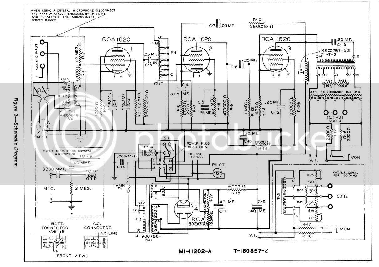
All we have to help us is RDH4 , Excel and the schematic.
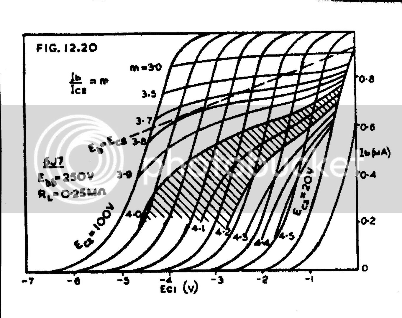
First of all I made some assumptions about the three stages from the resistor values given. V1 and V2 are very low current and the output stage V3 is high current. With any pentode, the ratio between the plate current and G2 current changes depending on the overall current, so we have to make a guess here using the handy chart from RDH4 page 515.
From this chart I decided to use a ratio of 4 for V3 and 4.3 for V1, ( V2 would be similar). Starting with V1 first, I started a spreadsheet with a range of B+ values ranging from 260 to 200 (for the table I deleted the least relevant).
Next I used the info from RDH4 which shows that the G2 loadline can be drawn on the triode characteristic when you change the scale according to the ratio:-
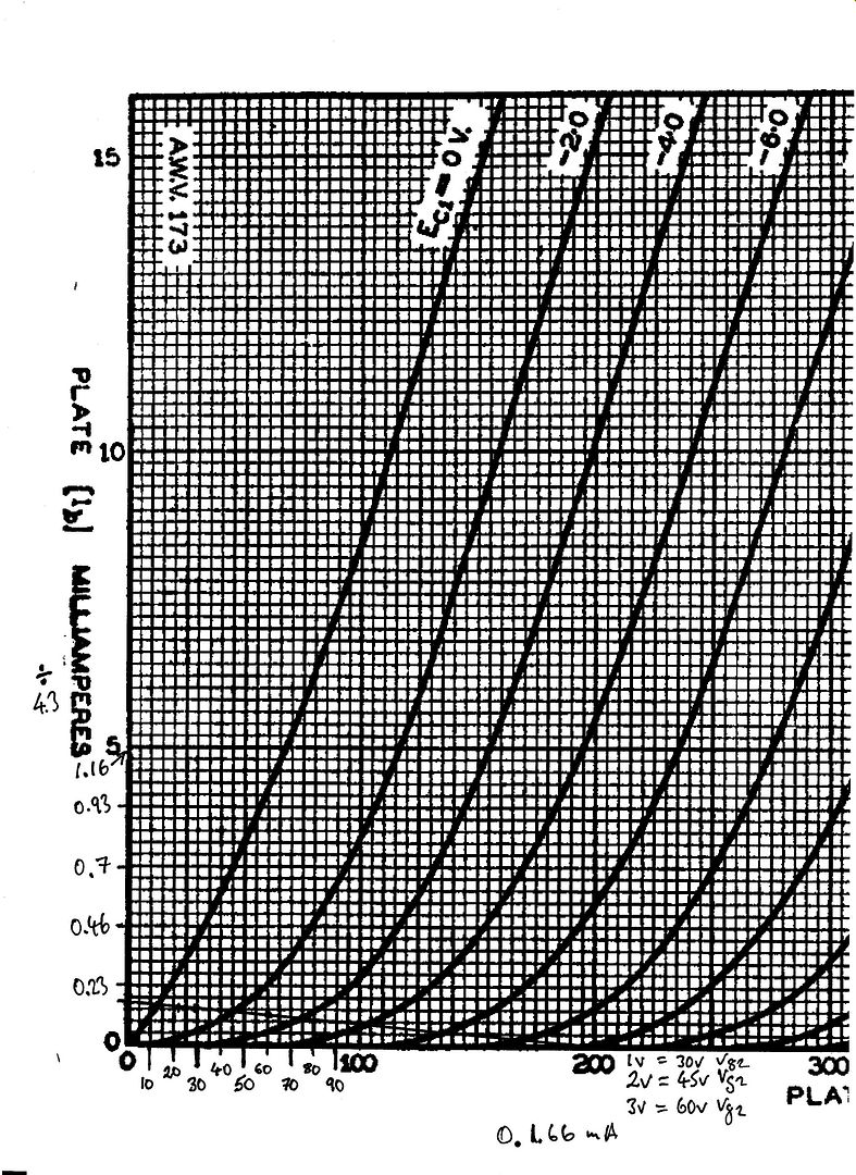
Here you can see that I divided the current scale by 4.3 to give those odd values and at the bottom there is the 1.2M g2 resistor load line.
I put the values for 200V into the spread sheet and calculated the voltage drops and hence the current. You then multiply the g2 current by the ratio to get the plate current. With the total current you have the cathode current and hence the cathode voltage.
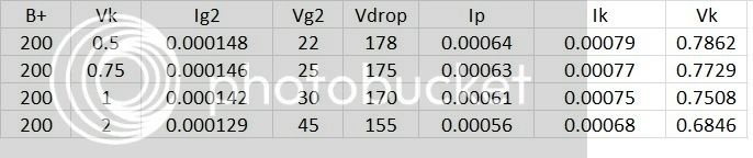
From the table you can see that the measured G1 voltage from the chart and the calculated voltage from the table coincide at somewhere between 0.75V and 0.8V, this seems like sailing too close to the wind to me and I would not have designed it that way myself. I checked these figures on an actual circuit and they are correct at ~0.7mA.
Actual voltages for V1 are:-
B+208V, Vp=76V, Vg2=25V Vk=0.74, current ratio=3.93
I did the same thing with V3 but as I had very little idea of what the B+ was, I had to use the maximum dissipation figures to give me an upper limit. I used the Radiotron version of the data from Frank's site. Here it says a 6J7 has 0.75W plate max and 0.1W g2max.
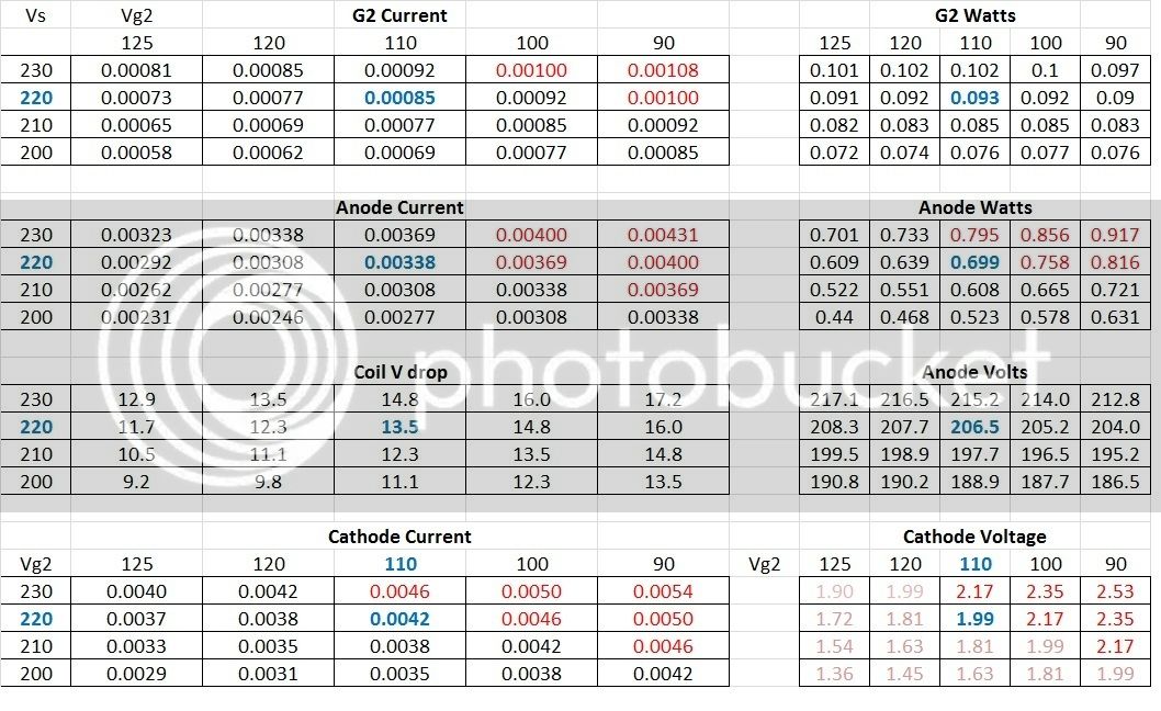
These figures are all obtained with simple ohms law from voltage drops, nothing fancy. The red figures exceed the spec and the blue figures are the estimate. After this I made the circuit with a 4k load (no choke handy) and the actual figures are:-
B+ 222V, Vp=208V, Vg2=100V, Vk= 2.07. Wp max =0.728W, Wg2max= 0.0938W, in the end the current ratio was 3.73 which accounts for the error between 110V and 100Vg2.
I will be posting more on the gain of these tubes later on, but I must say that it was a surprise to me that the designer went to such extremes. I think that he/they maximised the gain of all the stages so that they could use lots of feedback to kill the noise but still have sufficient gain. Whether it is actually 90/95dB we shall see.
I hope this is not too nerdy for most of you, but electronics is that way inclined!
Best
DaveP
There is mostly hype on the net and a youtube demo, but what hard facts there are have been supplied by Doug at EMRR.
This is what we know:-
OPT is 48k:500, IPT is 50/250:50k, Choke DCR is 4k, Choke inductance is 400Henries.
All we have to help us is RDH4 , Excel and the schematic.

First of all I made some assumptions about the three stages from the resistor values given. V1 and V2 are very low current and the output stage V3 is high current. With any pentode, the ratio between the plate current and G2 current changes depending on the overall current, so we have to make a guess here using the handy chart from RDH4 page 515.

From this chart I decided to use a ratio of 4 for V3 and 4.3 for V1, ( V2 would be similar). Starting with V1 first, I started a spreadsheet with a range of B+ values ranging from 260 to 200 (for the table I deleted the least relevant).
Next I used the info from RDH4 which shows that the G2 loadline can be drawn on the triode characteristic when you change the scale according to the ratio:-

Here you can see that I divided the current scale by 4.3 to give those odd values and at the bottom there is the 1.2M g2 resistor load line.
I put the values for 200V into the spread sheet and calculated the voltage drops and hence the current. You then multiply the g2 current by the ratio to get the plate current. With the total current you have the cathode current and hence the cathode voltage.

From the table you can see that the measured G1 voltage from the chart and the calculated voltage from the table coincide at somewhere between 0.75V and 0.8V, this seems like sailing too close to the wind to me and I would not have designed it that way myself. I checked these figures on an actual circuit and they are correct at ~0.7mA.
Actual voltages for V1 are:-
B+208V, Vp=76V, Vg2=25V Vk=0.74, current ratio=3.93
I did the same thing with V3 but as I had very little idea of what the B+ was, I had to use the maximum dissipation figures to give me an upper limit. I used the Radiotron version of the data from Frank's site. Here it says a 6J7 has 0.75W plate max and 0.1W g2max.

These figures are all obtained with simple ohms law from voltage drops, nothing fancy. The red figures exceed the spec and the blue figures are the estimate. After this I made the circuit with a 4k load (no choke handy) and the actual figures are:-
B+ 222V, Vp=208V, Vg2=100V, Vk= 2.07. Wp max =0.728W, Wg2max= 0.0938W, in the end the current ratio was 3.73 which accounts for the error between 110V and 100Vg2.
I will be posting more on the gain of these tubes later on, but I must say that it was a surprise to me that the designer went to such extremes. I think that he/they maximised the gain of all the stages so that they could use lots of feedback to kill the noise but still have sufficient gain. Whether it is actually 90/95dB we shall see.
I hope this is not too nerdy for most of you, but electronics is that way inclined!
Best
DaveP
