Recapping Altec 525A

GroupDIY Audio Forum

Help Support GroupDIY Audio Forum:

This site may earn a commission from merchant affiliate links, including eBay, Amazon, and others.
I recently stumbled onto this document in another thread here. It's got a rundown on the variations on the 21 series capsule. 21D is rated at 150db, 21BR220 is rated at 200db,m and there's a few in between. I have a pair of 21Ds, a pair of 21BR150's and I think a pair of 21BR180's, and a handful of 29B cardioid capsules, which I don't know the SPL rating for.

As for using a mic in front of a kick drum, a pop-filter can provide some protection from the blast.
 

Attachments

  • Altec 21 Capsules.pdf
    201.3 KB
150 dB is pretty ridiculous. I doubt any of the situations im using these in will come close to that.

Some testing showed that one of my mics which is brighter has the correct values for polarization voltage and B+ but the heater voltage is hard to evaluate in circuit.

The second mic was way low on polarization (~110VDC instead of the 200VDC expected) and the B+ is about 20% too high.

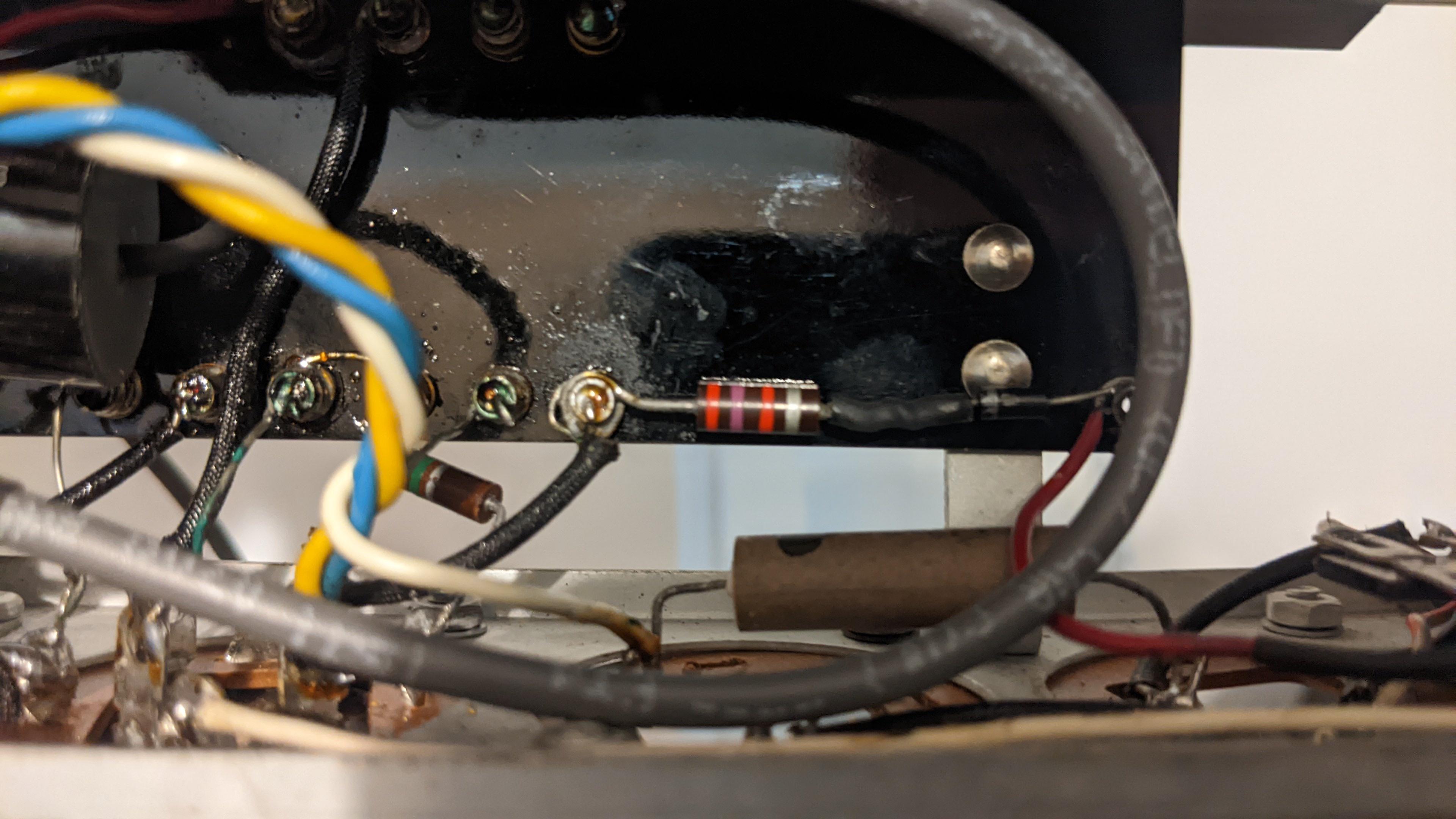
The first one has an ancient looking diode for the H+. Never seen one like this.

1696191279084.png
 
I have not known IRC, the International Resistance Company and the maker of that part, to make other than resistors back then. But the red and black end fills is indicative of polarity, so this is a new one for me. I also found that International Rectifier made selenium high-voltage rectifiers in a similar tubular package, albeit not exactly as pictured above.
 
150 dB is pretty ridiculous. I doubt any of the situations im using these in will come close to that.

Some testing showed that one of my mics which is brighter has the correct values for polarization voltage and B+ but the heater voltage is hard to evaluate in circuit.

The second mic was way low on polarization (~110VDC instead of the 200VDC expected) and the B+ is about 20% too high.

The first one has an ancient looking diode for the H+. Never seen one like this.

View attachment 115159
150dB spl is a lot. These were touted as measurement mics and NASA used them a lot.

All the info I have shows that component as a diode, or at least doing the job of one. Some of mine already had that replaced with a newer diode, but for uniformity I replaced them all anyway. Had to add a resistor in series to get the voltage to schematic spec (I think there's a post on the archived "greg's tech journal" thread over at the electrical audio forum that I gleaned this from)

Here's how it looks in mine:
FYtKL01.jpg


-110vdc instead of 200vdc seems bizarrely off to me. I'd need to consult the schematic and see if I can make sense of how that could happen (I'm kind of a novice so no promises) I opened up the connector on the mic cable and tested the voltages there, maybe that's worth a try.
It’s positive 110VDC not negative, I used the little ~ to signify “around this value”. Sorry for the confusion.

I’m definitely still confused about that “diode” but given the age it could be a selenium diode in a weird package. It’s definitely working as intended
 
It’s positive 110VDC not negative, I used the little ~ to signify “around this value”. Sorry for the confusion.

I’m definitely still confused about that “diode” but given the age it could be a selenium diode in a weird package. It’s definitely working as intended

That's what I get for trying to read things in the morning.
 
@thecr4ne, I'm rebuilding a couple of 525 psu's and in place of the selenium rectifier (RS1), I'm using two 1N4001's and a 1k resistor and for the the rectifier that looks like a resistor (RS2), I'm using an 1N4004 and 300 ohm resistor. With those in place but disconnected from the smoothing electrolytic capacitors (C3/C5), the voltages are stable, but when I connect the resistors to the smoothing capacitors, the voltages at C5 and C3 just keep climbing... Keep climbing... Over 400 volts on C5 and over 300 volts on C3. At first I figured I just didn't have big enough resistors after the diodes, so I put 47k resistors after both diodes, but that didn't make any difference. The other odd thing I noticed was when the resistors I added after the diodes are disconnected from C3/C5, the diodes measure correctly meaning current is only forward biased, but once I hook the diode/resistors to C3 or C5, the rectifier diodes become reverse biased as well. I don't know enough to know if that's correct or not. Did you deal with any of these kinds of issues when working on your 525s?
 
Back
Top