Relay Mute

GroupDIY Audio Forum

Help Support GroupDIY Audio Forum:

This site may earn a commission from merchant affiliate links, including eBay, Amazon, and others.

Bo Deadly

Well-known member
Joined
Dec 22, 2015
Messages
3,266
Location
New Jersey, USA
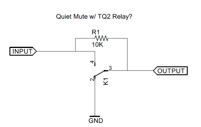
I need a mute circuit so I came up with the following:
QrnieWl.png


But a cursory search on the Net and in books shows circuits that are quite different. Is the above circuit flawed in some way?

It seems to me the 10K should minimize the effect of a DC offset causing a pop noise. This circuit would be on outputs so there should not be significant gain after the mute. I think I would rather live with a little pop noise than with the distortion of a soft changeover JFET circuit.

Thoughts?
 
10K Might degrade the mute kill depth depending on ground integrity and rest of the circuitry.

I might be tempted to go a little higher impedance but not a lot.

JR .
 
doesn't that play on the input impedance of the next stage?

If your next stage has a 10K input impedance then you'll halve your voltage during regular playback.

If you really want to play games like this, read some of doug self's small signal book. It has some good muting circuits etc.

/R
 
squarewave said:
I need a mute circuit...

It seems to me the 10K should minimize the effect of a DC offset causing a pop noise.
That just wouuldn't work. I mean it wouldn't do any reduction of clicks, because when ON the output receives the whole signal, including whatever offset, and when MUTE, the output is grounded.
There are only two ways to get rid of switching clicks:
a) completely eliminate the offset, either with a coupling cap or with a servo
b) implement soft switching, which is possible with FET's but is not without cons
 
A relay-mute always might create clicks when a signal is present, apart from the DC problem which should be very easy to solve. For my liking the best mute circuit was in the flying faders automation. They used fast LDRs, but I don't know the whole circuit from memory. It might be a problem to get hold of the opto couplers due to the recent EU ban which was discussed in a different thread. Other than that it seems pretty easy once the schematic is there, not too expensive and providing a good long-term reliability. And it sounded really good to my ears when I was working with it.

Michael
 
It is impossible to answer without knowing more about where the signal is coming from and where it it going.

If I read the OP correctly he prefers a fast switch (click) to slow switching (fet, VCA, LDR) because of distortion? AFAIK only JFET shunts can cause distortion during transition, but adding some of the audio into the gate drive (-6dB) can reduce that distortion.

If the input signal is DC coupled and not trimmed to exactly 0V, there can be a click/thump between the muted ground and unmuted DC voltage. A cap coupled input and output with perhaps another added bleed resistor should avoid DC steps.

As mentioned a JFET switch can be linearized to reduce distortion during a slow transition. Another circuit trick to de-click fast hard mutes, is to use HF pre-emphasis before the mute switch, then complementary de-emphasis after the switch. That way the click caused by muting will get rolled off by the de-emphasis.  (This works but is not free,,, it consumes some HF headroom.)

I have done many mute circuits over the years. It is important to manage DC offsets, while the fancy circuit tricks are more often used in noise gates.

JR


Latest posts

Back
Top