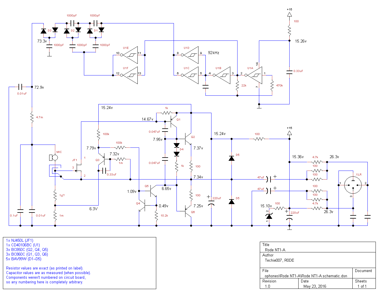
I don't understand your question. The capsule is connected to the gate of the FET. There is nothing more to it.Can someone help me understand the microphone input symbol? When i lool at the PCB pictures, i don't get it. Where is the source of JFET connected through that via?
You are using an out of date browser. It may not display this or other websites correctly.
You should upgrade or use an alternative browser.
You should upgrade or use an alternative browser.
Rode NT1A schematic?
- Thread starter bkdog
- Start date


Help Support GroupDIY Audio Forum:
This site may earn a commission from merchant affiliate
links, including eBay, Amazon, and others.
Value is not critical. 10 to 47nF is good. They must be ceramic type with very short connections. Best implementation is soldering them directly to the XLR pins.Also what are the suitable values of these capacitors?
ok. Thanks. Got it.I don't understand your question. The capsule is connected to the gate of the FET. There is nothing more to it.

i think they are type of low pass filter. High value may attenuate the signal and very low value will increase the noise. Am i correct?Value is not critical. 10 to 47nF is good. They must be ceramic type with very short connections. Best implementation is soldering them directly to the XLR pins.
No doubt about teh 1Gig, but I don't know for the supposed 1Meg...are these resistors 1 Giga ohm and 1 Mega ohm respectively?


Sort of. They interact with the cable's impedance to short out interference.i think they are type of low pass filter.
It would need to be very large for attenuating the HF part of the signal. And it will not increase noise. If there is no interference, it will not do anything. If there is interference, it will be attenuated.High value may attenuate the signal and very low value will increase the noise. Am i correct?
saint gillis
Well-known member
Hey , I'm trying to repair one of these. It felt on the ground, and now is making a huge white noise at the output.
I have removed the 100r resistor just before D5, and removed the 100r resistor feeding the 40106, and it was still doing the same noise, I've replaced D5 diodes and the zener, still noisy.
Does anyone know how I could repair it, is there a way to inject a signal to find the culprit ?
I have removed the 100r resistor just before D5, and removed the 100r resistor feeding the 40106, and it was still doing the same noise, I've replaced D5 diodes and the zener, still noisy.
Does anyone know how I could repair it, is there a way to inject a signal to find the culprit ?
Last edited:
You can inject signal directly into the gate of the FET, via a capacitor (typically 1-10nF).Does anyone know how I could repair it, is there a way to inject a signal a find the culprit ?
Have you checked all the DC voltages?
saint gillis
Well-known member
Thank you for the method,
All voltages are correct, I've injected a signal, signal restitution at the output is correct, with almost unity gain.
Noise is still huge, even with the mic preamp gain where the NT1-A is plugged at minimum.
All voltages are correct, I've injected a signal, signal restitution at the output is correct, with almost unity gain.
Noise is still huge, even with the mic preamp gain where the NT1-A is plugged at minimum.
Then it can be many things. Most probable causes of noise:Thank you for the method,
All voltages are correct, I've injected a signal, signal restitution at the output is correct, with almost unity gain.
Noise is still huge, even with the mic preamp gain where the NT1-A is plugged at minimum.
- 0.33uF capacitor disconnected/broken
- FET defective
- Q5 defective
- 220uF cap disconnected or defective
BTW, I assume that the resistors marked 1m are actually 1 Megohm, not 1 milliohm.

saint gillis
Well-known member
Hahah yes indeed they are, electrolytics replaced.. for the rest I'm gonna check, thanks a lot !
saint gillis
Well-known member
So I've replaced 0,33µ, G5, Fet, Q3
Still noisy
Is it normal that it's noisy with the 100r to D5 and the 100r to the 40106 removed (48V only going to the zener and the first 220µ) ?
Still noisy
Is it normal that it's noisy with the 100r to D5 and the 100r to the 40106 removed (48V only going to the zener and the first 220µ) ?
Last edited:
Unfortunately, it can be... The voltage rail must be much higher than normal, probably 30V instead of 15, but it's not an issue.So I've replaced 0,33µ, G5, Fet, Q3
Still noisy
Is it normal that it's noisy with the 100r to D5 and the 100r to the 40106 removed (48V only going to the zener and the first 220µ) ?
saint gillis
Well-known member
The resistor going to the zener is still here, it's the resistors feeding the rest of the circuit that I tried to disconnect from the 15V rail..
Ah, ok.The resistor going to the zener is still here, it's the resistors feeding the rest of the circuit that I tried to disconnect from the 15V rail..
Then I would suspect one of the 47 uF or diode D5.
saint gillis
Well-known member
All replaced , didn't change..Ah, ok.
Then I would suspect one of the 47 uF or diode D5.
saint gillis
Well-known member

There is so little left... I guess you can eliminate the resistors from the list of suspects
saint gillis
Well-known member
I've put this exact same last circuit on a breadboard, and it generates the same kind of noise (from the zener I suppose)
I guess on a working NT1A, some low output impedance circuit drives the outputs of the mic and takes the place of the psu noise?
I guess on a working NT1A, some low output impedance circuit drives the outputs of the mic and takes the place of the psu noise?
Similar threads
- Replies
- 4
- Views
- 324