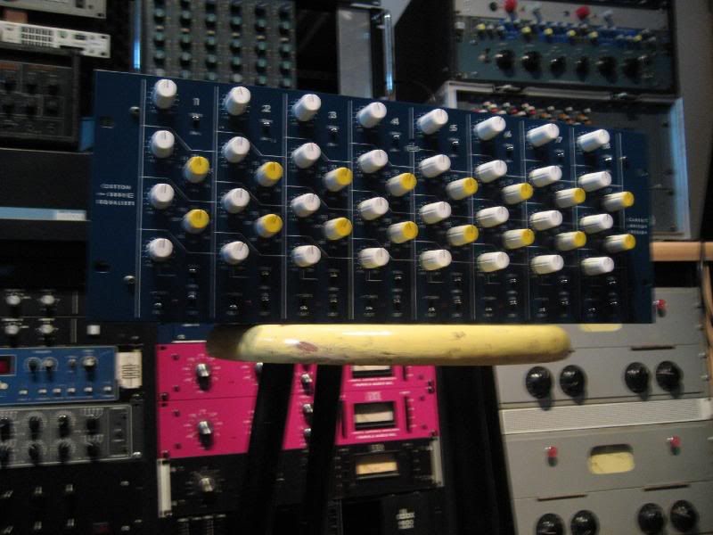
S800 Support Thread

GroupDIY Audio Forum

Help Support GroupDIY Audio Forum:

This site may earn a commission from merchant affiliate links, including eBay, Amazon, and others.
Great looking build there , Matta , as usual!

Did you just tie the input xlr pin 1's direct to chassis?

I'm thinking now about drilling my enclosure, and wondering if i need to implement an earth lift switch between pin 1 and chassis . It's something I've gotten into doing with my 1176 and GSSL , but maybe it isn't necessary in this case...sounds like yours is pretty clean...have you auditioned it in a chain with any other units yet?

I actually didn't do an earth-lift switch my calrec 1549, but that was mainly because I couldn't understand why that circuit has no xlr input to 0 volt connection anyway...

Cheers

nEon
 
Hi nEon,

I tied the Pin 1's at direct to the chassis as per the RANE doc. I've done this is every piece of DIY gear I've built with great success thus far, and I'm a stickler for noise... you can see some of my previous posts where others have said it is 'ok' and I've gone deeper in to lower noise/hum it in ALL my gear as best I can.

In my listening tests I've sent signals out of my Lynx Aurora AD/DA into the S800 and back through Pro Tools, no other additional bits, but would gladly do so if you think it will help the cause.

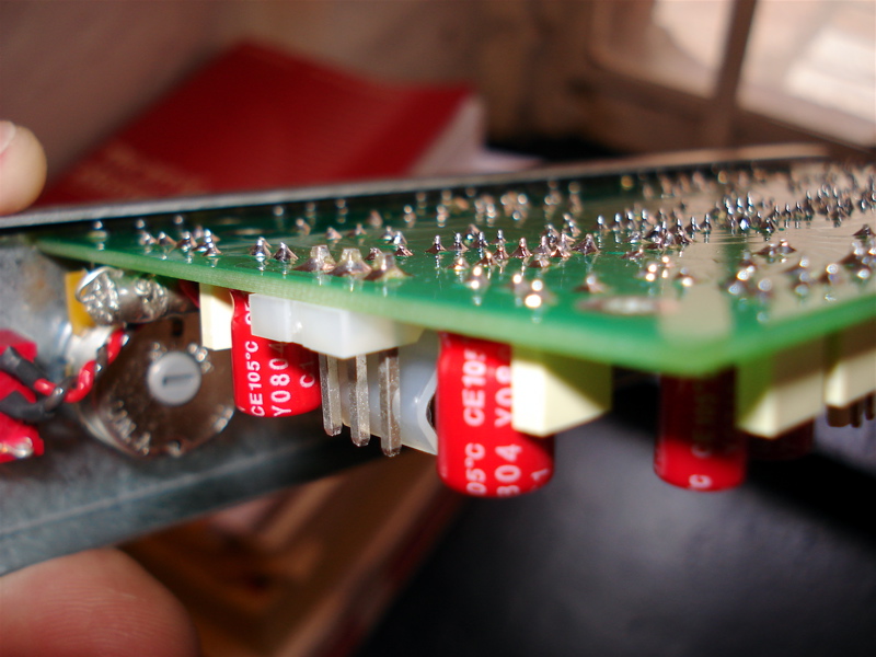
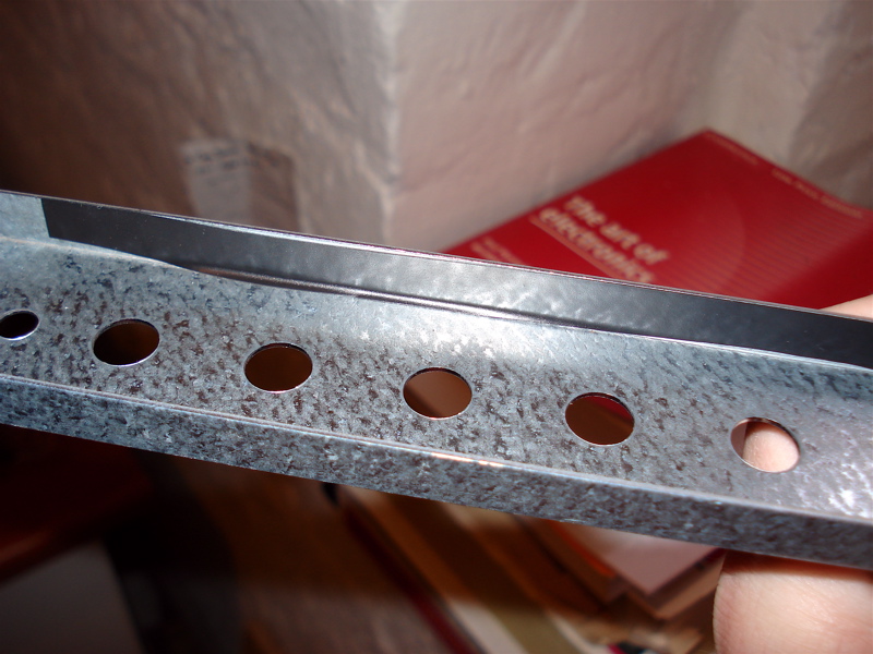
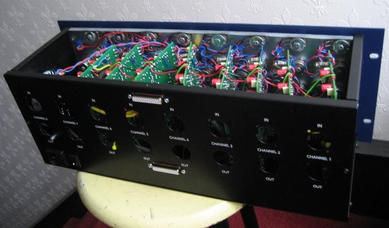
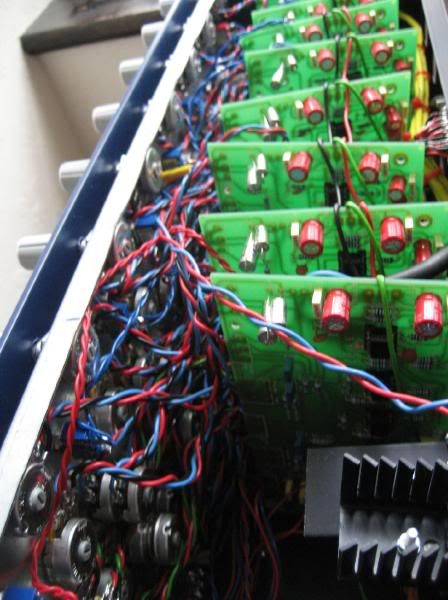
Also since I'm here... a few other words of caution.... if you mount the pots on board with Purusha's racks you BETTER cut off the excess length on the pot legs as they WILL short out... I cut them short and then just to be safe added electrical tape to the inside of the rack, even though there is 1-2mm's clearance, better be safe than sorry.

S800_clearance.jpg


S800_tape.jpg


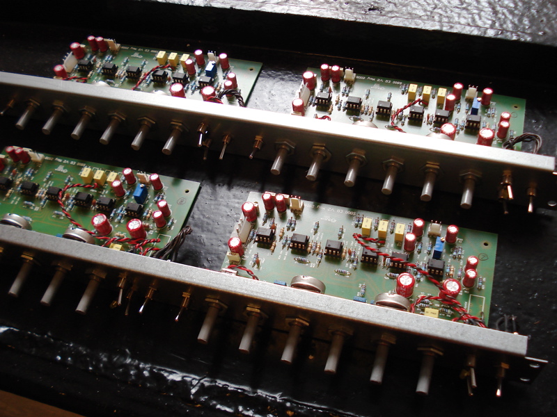
Here is a pic of the boards from the component side mounted to the sub frame.... got to give a kudos to Colin again, bough his kits and they are great, great quality components and they sound great to boot.

S800_PCB.jpg


The 100k dual gang pots should be linear or log?

REV Log

Cheers

Matt
 
matta said:
Hi nEon,

I tied the Pin 1's at direct to the chassis as per the RANE doc.

Am I understanding this correctly?  You went from the input XLR Pin 1 right to the screw of the XLR/chassis?  I can't see it in your pic, but that's what I usually do.

Thanks,
Sig
 
Siegfried Meier said:
matta said:
Hi nEon,

I tied the Pin 1's at direct to the chassis as per the RANE doc.

Am I understanding this correctly?  You went from the input XLR Pin 1 right to the screw of the XLR/chassis?  I can't see it in your pic, but that's what I usually do.

Thanks,
Sig

Correct... though in my case it is neater to solder Pin 1 to the chassis tab that the Ampehnol Connectors I use have. This in turn is connected too the shell, which is screwed to the chassis. I always use a dremel to take off the coating around the holes as well to make sure it meets the metal and then ohm it all out to be sure I've got full continuity between all ground points.

Cheers

Matt
 
Cheers Matta..mmm ..more nice pics!

great quality components and they sound great to boot

So you are diggin' those red dubliers for audio then?

They are really easy to get in the uk , and I must get around to trying a build using only that type of electro. Almost stuffed my first s800 , using elna stargets , and I have a matched 2nd board ready to go with FC's...also just got some of those metallic blue pana ECA series (very cheap) to try .

I thought the s800 looked like a nice neat little circuit to use as a test bed for all these caps ; I've read so many posts here discussing cap brands!

Thanks again for sharing the info!

Cheers

nEon.


First 2 boards completed over here...just watching the snow storm outside while doing some GREAT EQ's.

When i say great i mean 2 basic things....inexpensive and great sounding.

I couldnt afford the Audio Maintenance kits...so ended up with Small bear pots and sourcing the rest...locally.

i used Rubycons, Panasonic FC, Eros and vishay caps
i paid 35$ in parts for 4 eQ's + 4 pcbs....total 75$ for 4 great EQ's.

Just listened to the 1st and it sounds very nice...lots of colours and character!!

Tip my hat to JC and Peter C.
 
Dr nEon said:
I thought the s800 looked like a nice neat little circuit to use as a test bed for all these caps ; I've read so many posts here discussing cap brands!

What where the original caps?
 
Nice work inputoutput and Matta!!!

I am glad all small problems can be solved around my cases. They usually are!  ;)

BTW Matta, I noticed you used ceramic caps instead of Styros in yours. Do I see this right?
 
Hey matta  , or anyone else  , i noticed the 470 caps in Colins
kits are 16 v , not sure where the schematic is at the moment  , but
this voltage is o.k. for whatever part of the circuit it's in ?
 
Purusha said:
Nice work inputoutput and Matta!!!

I am glad all small problems can be solved around my cases. They usually are!  ;)

BTW Matta, I noticed you used ceramic caps instead of Styros in yours. Do I see this right?

No I used styro's for the top bands, only ceramics are the feedback/compensation caps around the opamps, which is typical of most audio designs.

Greg, RE the voltage ratings of the 470uF's, the schematic calls for 6V here pretty sure 16V is ample. The 470uF's sit on the output of U1, not across the PSU rails.

RE schematics they are all in the Group DIY Gmail account.

Oh and HAPPY NEW YEAR ALL!

Cheers

Matt
 
thanks matta , i first saw the decoupling on the psu / opamps in the bottom left corner of the schemo
but i see they are back to back to non polerize after the first opamp , but still makes for a big cap eh ?
 
okgb said:
thanks matta , i first saw the decoupling on the psu / opamps in the bottom left corner of the schemo
but i see they are back to back to non polerize after the first opamp , but still makes for a big cap eh ?

Indeed

 
I just finished up a friend's S8001 (he built it, I de-bugged it)
Here are a couple little tips that I found:
Matta showed us all about cutting down the leads on the pots - make sure that you trim up all the ends of all the components.  My buddy had a bunch of things that got jammed in to the case, like the trim pot.  Chop it all short.

Make sure all your solder joints are good.  It seems like a no-brainer, but it can make all the difference.  Also with the 8-pin sockets, try to get them flat and snug into the PCB.  My buddy managed to solder a socket in but only actually solder in 7 of the 8 pins.

Finally, make sure all your caps and ICs are in the right direction.  Possibly the biggest no-brainer, but my friend managed to put his 5532 in backwards.  It actually melted the socket while going up in smoke.
 
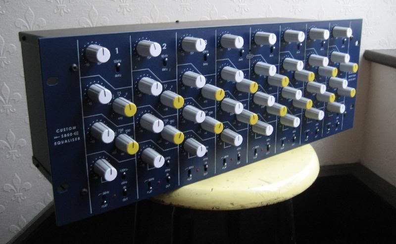
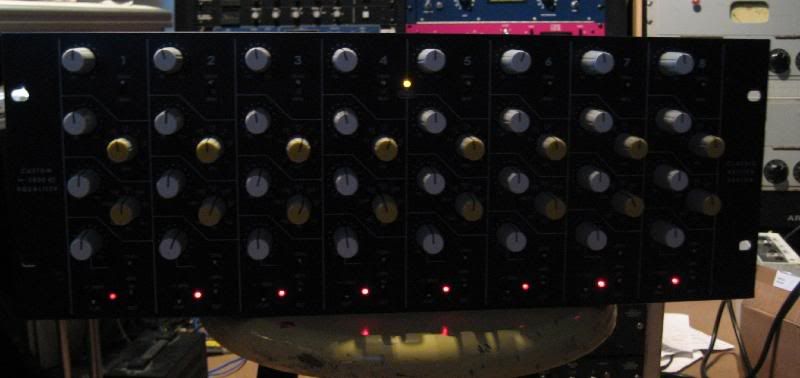
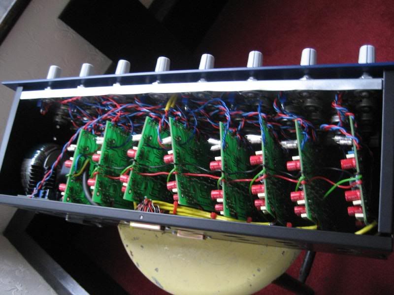
Completed S800-8, boy it's a tight squeeze! I gave up on the brackets that hold the PCB's as I just couldn't get my hands in!
Front-1.jpg

Back
Back.jpg

Powered for the first time
Powered.jpg

Top
Top.jpg

Guts
Guts-1.jpg

In great company as always :)
Inthestudio.jpg
 
Brolik said:
I switched the 2k2s to 2k7s and got 18.25v on one side and 18.35v on the other.  The formula for the regulators spit out much closer to 3k, but the 2k98 i used gave me over 19v.

I could use 5k trimmers in place of those 2.2k resistors and dial in the proper voltage?
 

Latest posts

Back
Top