matta said:
When I get a chance I'll do so, stuck in sessions at the moment... if someone else has time they can. but I'll do it when I get a chance.
Matt
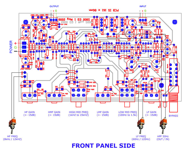
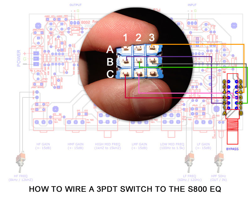
The PCB is designed for a switch with two rows of six contacts, from the front (pot mounting edge):
Row two switches to either, row one (out) or row three (in) likewise for row five, switches between row four or row six.
Not all poles are needed, the three poles are:
1, Both sides of row two only needs to switch to row three. (switch on position)
2, Row five needs only to make contact with row four on one side (right from the pot mounting edge) (switch off position)
I wish I could use a graphics program! hehehehehe


![Soldering Iron Kit, 120W LED Digital Advanced Solder Iron Soldering Gun kit, 110V Welding Tools, Smart Temperature Control [356℉-932℉], Extra 5pcs Tips, Auto Sleep, Temp Calibration, Orange](https://m.media-amazon.com/images/I/51sFKu9SdeL._SL500_.jpg)


