You are using an out of date browser. It may not display this or other websites correctly.
You should upgrade or use an alternative browser.
You should upgrade or use an alternative browser.
SB4000 Support Thread
- Thread starter ruckus328
- Start date
Help Support GroupDIY Audio Forum:
This site may earn a commission from merchant affiliate
links, including eBay, Amazon, and others.
MLAudio
Member
- Joined
- Oct 18, 2010
- Messages
- 10
Harpo said:"for an easier fix an about 3K3...4K7 fixed resistor at the meter terminal" would have done the same without cutting a pcb trace.MLAudio said:Added a 5K resistor in series with VR17 and all is well in the land of gain reduction metering. For those who want or need this fix, here is what I did. I cut the trace on the back side of the PCB between C121 and VR17 Pin 1 (CCW) and then soldered the resistor on the backside between those points. This allowed me to correctly complete Calibration Step 4) Meter/Ratios with the 1ma (slightly less in reality) Hairball compression meter.
You are absolutely right. I thought about that at first, but since my gear is always moving around from trucks to venues to studio (I do mainly live recording), I didn't want anything flopping around. For most people your suggestion is the best.
dacapitan
Well-known member
I have the unit passing clean audio in bypass mode and with the compressor in, gain seems to be working fine but threshold only shows any sign of compression at extreme levels (-20) which I think can be explained by the problem below. I have begun to calibrate the unit but I have run into a problem at step 3.
I get a reading of 0.740VAC at TP 8 and TP 10
I get 0v reading at TP11 and TP12 with no effect from VR7 & VR8.
I have tried to look for solutions through the thread and noticed Mica had the same issue, but the conversation led to a dead end. I know ruckus328 did mention to buzz out from The input to TP11 & 12
-- but I must admit I am not that great at reading schematics either. I am struggling to understand where the XLR input meets the Internal Left and Right Side Chain on the schematic, so I can attempt to buzz it out? Any help would be appreciated
I really am trying my hardest/best to understand this, having completed 4 builds this has by far been the most challenging and patience testing.
Harpo
Well-known member
Mikes or mine (see previous page)?dacapitan said:I have begun to calibrate the unit but I have run into a problem at step 3.
Unit powered on, HPFilters set to off position, External key disabled, sine test signal connected to XLR-inputs ?I get 0v reading at TP11 and TP12 with no effect from VR7 & VR8.
Check for same AC voltage U2a-pin1 as TP8 and same AC voltage U1a-pin1 as TP10.
Check for same AC voltages arriving at the 20-pin connector J6/J18-pin11 and pin18.
Check for same AC voltages arriving at the 2x6 HPF switch poles pin1 and pin7.
Check for same AC voltages arriving at the 20-pin connector J6/J18-pin13 and pin17.
Check for same AC voltages arriving at the external key relais K6-pin4 and pin9.
If any of these tests fail, fix it (bad solder connection, broken part, connector not connecting, ...) before continuing.
Now adjust TP11 and TP12 for same AC voltages by trimming VR7 and VR8.
dacapitan
Well-known member
Harpo said:Mikes or mine (see previous page)?dacapitan said:I have begun to calibrate the unit but I have run into a problem at step 3.
Unit powered on, HPFilters set to off position, External key disabled, sine test signal connected to XLR-inputs ?I get 0v reading at TP11 and TP12 with no effect from VR7 & VR8.
Check for same AC voltage U2a-pin1 as TP8 and same AC voltage U1a-pin1 as TP10.
Check for same AC voltages arriving at the 20-pin connector J6/J18-pin11 and pin18.
Check for same AC voltages arriving at the 2x6 HPF switch poles pin1 and pin7.
Check for same AC voltages arriving at the 20-pin connector J6/J18-pin13 and pin17.
Check for same AC voltages arriving at the external key relais K6-pin4 and pin9.
If any of these tests fail, fix it (bad solder connection, broken part, connector not connecting, ...) before continuing.
Now adjust TP11 and TP12 for same AC voltages by trimming VR7 and VR8.
Thanks for the reply Harpo - I appreciate it alot,
I have tested all the points you have mentioned above and get the same Voltage as TP8 and TP10
Although I get 0v at K6-pin4 and pin9 but I get the same voltage as TP8 and TP10 at K6-Pin10 and Pin3 according to the datasheet below
http://www.mouser.com/ds/2/418/NG_SS_108-98002_W_P2-196265.pdf
Which according to the schematic would make sense as to why there is no voltaqe at TP11 and TP12.... but the question now is, how to get the voltage to carry from k-6 Pin3 and 10 to Pin4 and Pin9?
Harpo
Well-known member
dacapitan said:Although I get 0v at K6-pin4 and pin9 but I get the same voltage as TP8 and TP10 at K6-Pin10 and Pin3 ...
but the question now is, how to get the voltage to carry from k-6 Pin3 and 10 to Pin4 and Pin9?
This. Your unit is switched for sidechain operating an external key signal (with obviously no external signal present) and the relais K6 seems to be operating correctly to do so.Harpo said:... External key disabled, ...
dacapitan
Well-known member
Harpo said:dacapitan said:Although I get 0v at K6-pin4 and pin9 but I get the same voltage as TP8 and TP10 at K6-Pin10 and Pin3 ...
but the question now is, how to get the voltage to carry from k-6 Pin3 and 10 to Pin4 and Pin9?This. Your unit is switched for sidechain operating an external key signal (with obviously no external signal present) and the relais K6 seems to be operating correctly to do so.Harpo said:... External key disabled, ...
Spot on Harpo! The way I understood the key switch to work is obviously in reverse to what I thought. Cant thank you enough!! You are so helpful - very much appreciated!!
Bowie
Well-known member
- Joined
- Jun 22, 2012
- Messages
- 369
Does anyone know what might cause the gain knob to be bypassed/non-functioning?? I have fully functioning compression and the bargraph monitors the input. But, no matter where I have the I/O switch or the Gain knob, the output doesn't change. I can hear it, but it's not adjustable. Any help is greatly appreciated.
Thank you.
Thank you.
Harpo
Well-known member
12VDC across the makeup pots outer pins?Bowie said:Does anyone know what might cause the gain knob to be bypassed/non-functioning??
Pots center pin varying voltage between 0...12VDC when you turn from CCW to CW position?
Same DC voltage arriving at the 20pin connector J18 pin10 and J6 pin10?
Same DC voltage arriving at left side of R123 (other/virtual ground side of R123 will measure 0V)?
Obviously not.I have fully functioning compression...
By default setting the bargraph is monitoring the right side output. Feeding both the left and right side with different program level would show this input/output and left/right side selector for the audio level bargraph operating correctly (or not)....and the bargraph monitors the input.
Nothing to do with the units compressing function.But, no matter where I have the I/O switch...
Audio output (assuming you are referencing this) with program signal above threshold will change with different ratio settings, no matter what makeup gain is dialed in. At least your unit is not in hard bypass mode, else the bargraph at any I/O L/R setting wouldn't response....or the Gain knob, the output doesn't change.
Whatever you may hear doesn't make much sense in this context.I can hear it, but it's not adjustable.
Bowie
Well-known member
- Joined
- Jun 22, 2012
- Messages
- 369
Harpo said:12VDC across the makeup pots outer pins?Bowie said:Does anyone know what might cause the gain knob to be bypassed/non-functioning??
Pots center pin varying voltage between 0...12VDC when you turn from CCW to CW position?
First, thanks for taking the time!! I have someone waiting on the completion of this build and I'm under pressure to finish it.
As far as the pot, yes, measurements go from 0-12vdc when panned.
It there any way to measure this without removing the main and panel boards and measuring them at the solder joints underneath?Same DCvoltage arriving at the 20pin connector J18 pin10 and J6 pin10?
Yes, it's 12vdc at one end of the resistor and 0 on the other.Same DC voltage arriving at left side of R123 (other/virtual ground side of R123 will measure 0V)?
The compression itself is functioning. I can hear it working correctly and responding as-expected to changes in threshold, ratio, etc. It's the make-up gain and output metering that are non-functional.Obviously not.I have fully functioning compression...
That has me even more stumped because it's definitely the input signal I'm seeing. The reason I can tell is that it does not change under heavy compression. The bargraph meter level does not go down when heavy compression is implemented, leading me to believe that it's showing the input. Also, these levels remain exactly the same when I flip the I/O switch.By default setting the bargraph is monitoring the right side output. Feeding both the left and right side with different program level would show this input/output and left/right side selector for the audio level bargraph operating correctly (or not)....and the bargraph monitors the input.
The left and right selection works correctly though and shows different levels for the left and right channels.
Correct, I didn't think it would. But, I expected to show the input and output levels respectively (unless it's reflecting something else that I'm not aware of).Nothing to do with the units compressing function.But, no matter where I have the I/O switch...
Yes, but what I am saying is the the Gain knob has no influence on the sound. It is not functioning, not affecting the gain at all when tuned. It's as if it's not even hooked up, but when I measured it, it's measuring 12vdc when open and 0 when closed.Audio output (assuming you are referencing this) with program signal above threshold will change with different ratio settings, no matter what makeup gain is dialed in....or the Gain knob, the output doesn't change.
What I am hearing out of this unit is normal audio compression that behaves very much like the SLL buss comp I worked on years ago. However, my Gain pot isn't working at all and the meter only shows input, even when it is switched to the output setting.Whatever you may hear doesn't make much sense in this context.I can hear it, but it's not adjustable.
Thanks again for the help, I hope I was able to clarify the specific issues taking place.
Harpo
Well-known member
0...12V DC offset arriving at R123 proves the 20pin connector pin10 conducting and 0V at the opamps inverting input shows usual behaviour of a working opamp. Measuring the inverting summer U13-pin7 without audio signal should show a varying negative voltage between 0V and -1.935V when varying the makeup pot. Case not, reflow the bad or missing solder connection of R123 (correct parts value 620K ?).Bowie said:It there any way to measure this without removing the main and panel boards and measuring them at the solder joints underneath?Same DCvoltage arriving at the 20pin connector J18 pin10 and J6 pin10?
Yes, it's 12vdc at one end of the resistor and 0 on the other.Same DC voltage arriving at left side of R123 (other/virtual ground side of R123 will measure 0V)?
But GR-meter is working correctly ? (VR17 dialed in for too low resistance might shunt down U16c)It's the make-up gain and output metering that are non-functional.
You measured this? You wouldn't be the 1st. with missing solder connection at relais K7....because it's definitely the input signal I'm seeing. The reason I can tell is that it does not change under heavy compression.
Describing previous assumption of a maybe bad solder connections at K7 (or SW3 or R130 parts value/solder connection) that prevents the relais to switch over for metering input side. Different from other compressors, the ratio circuit already injects a gain loss compensating voltage depending on ratio setting.The bargraph meter level does not go down when heavy compression is implemented, leading me to believe that it's showing the input. Also, these levels remain exactly the same when I flip the I/O switch.
Bowie
Well-known member
- Joined
- Jun 22, 2012
- Messages
- 369
Harpo said:0...12V DC offset arriving at R123 proves the 20pin connector pin10 conducting and 0V at the opamps inverting input shows usual behaviour of a working opamp. Measuring the inverting summer U13-pin7 without audio signal should show a varying negative voltage between 0V and -1.935V when varying the makeup pot. Case not, reflow the bad or missing solder connection of R123 (correct parts value 620K ?).Bowie said:It there any way to measure this without removing the main and panel boards and measuring them at the solder joints underneath?Same DCvoltage arriving at the 20pin connector J18 pin10 and J6 pin10?
Yes, it's 12vdc at one end of the resistor and 0 on the other.Same DC voltage arriving at left side of R123 (other/virtual ground side of R123 will measure 0V)?
But GR-meter is working correctly ? (VR17 dialed in for too low resistance might shunt down U16c)It's the make-up gain and output metering that are non-functional.
You measured this? You wouldn't be the 1st. with missing solder connection at relais K7....because it's definitely the input signal I'm seeing. The reason I can tell is that it does not change under heavy compression.
Describing previous assumption of a maybe bad solder connections at K7 (or SW3 or R130 parts value/solder connection) that prevents the relais to switch over for metering input side. Different from other compressors, the ratio circuit already injects a gain loss compensating voltage depending on ratio setting.The bargraph meter level does not go down when heavy compression is implemented, leading me to believe that it's showing the input. Also, these levels remain exactly the same when I flip the I/O switch.
Thanks Harpo, I checked/adjusted VR17 and it was ok. On U13 I wasn't sure what pin-7 was but I check the ones that might be it and didn't see any negative voltage, just levels close to 0. Before taking the main board out to re-solder I tried experimenting with some things. I went to give it a listen and run some test tones and discovered that my problem is compounded now as I'm no longer getting compression on the output signal, though the meter shows every nuance of the compression. It changes as I adjust the with the threshold, ratio, stereo/mono, sidechain, etc so I know it's reflecting actual compression. But, it's not apparent in the output signal. The output signal now just sounds like a several db reduced version of the input. Does that give you any ideas who what might be going wrong?
Thanks.
Harpo
Well-known member
U13=TL072. Its output pin7 is sending control voltage to the audio-VCAs. No high voltages here (50mV/dB). Just follow the pcb traces to the audio-VCAs, beginning with R118 (with maybe buffered voltage attenuators 6.1mV/dB for THAT218x VCAs in between) and look out for shorts and/or wrong/missing jumper settings for your secret type of audio-VCAs that might shunt down your control voltage. (I have neither an idea of your populated parts nor your signal level or if this misbehaviour might be frequency related from wrong value fitted caps).Bowie said:On U13 I wasn't sure what pin-7 was but I check the ones that might be it and didn't see any negative voltage, just levels close to 0.
Sidechain hopefully seems to be error free then. After removing possible errors on their way to the audio-VCAs and if sidechain- and audio-VCAs are the same type, you might pull one sidechain-VCA and exchange it with an audio-VCA to exclude a broken audio-VCA....though the meter shows every nuance of the compression. It changes as I adjust the with the threshold, ratio, stereo/mono, sidechain, etc so I know it's reflecting actual compression.
Bowie
Well-known member
- Joined
- Jun 22, 2012
- Messages
- 369
Thanks, I've been pulling it apart, triple checking for correct component values, shorts, correct jumpers, etc and I'm really at a loss. It still has no audible compression even though it can be seen on the meter. What might cause the signal to come through uncompressed even though the compression meter is showing what looks to be normal compression behavior as I adjust the knobs?Harpo said:U13=TL072. Its output pin7 is sending control voltage to the audio-VCAs. No high voltages here (50mV/dB). Just follow the pcb traces to the audio-VCAs, beginning with R118 (with maybe buffered voltage attenuators 6.1mV/dB for THAT218x VCAs in between) and look out for shorts and/or wrong/missing jumper settings for your secret type of audio-VCAs that might shunt down your control voltage. (I have neither an idea of your populated parts nor your signal level or if this misbehaviour might be frequency related from wrong value fitted caps).Bowie said:On U13 I wasn't sure what pin-7 was but I check the ones that might be it and didn't see any negative voltage, just levels close to 0.
Sidechain hopefully seems to be error free then. After removing possible errors on their way to the audio-VCAs and if sidechain- and audio-VCAs are the same type, you might pull one sidechain-VCA and exchange it with an audio-VCA to exclude a broken audio-VCA....though the meter shows every nuance of the compression. It changes as I adjust the with the threshold, ratio, stereo/mono, sidechain, etc so I know it's reflecting actual compression.
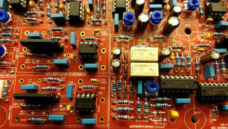
I can post any other pics that might help.
Just a thought, and i did this on one of the ones i built. The Inputs are the ones in the MIDDLE of the board the outputs are on the left (if looking at it from the front) If you hook it up in reverse it passes audio in bypass but no compression. I spent a day trying to find errors once only to realize this. Very embarrassing moment in the shop lol.
Bowie
Well-known member
- Joined
- Jun 22, 2012
- Messages
- 369
When I initially wired it I had done that too, but caught it before hooking up the main board. Thanks for the help though.sr1200 said:Just a thought, and i did this on one of the ones i built. The Inputs are the ones in the MIDDLE of the board the outputs are on the left (if looking at it from the front) If you hook it up in reverse it passes audio in bypass but no compression. I spent a day trying to find errors once only to realize this. Very embarrassing moment in the shop lol.
I'm starting to think it must be a component failure as I've going over this board an endless number of times. I really hope it's my own error as it would be easier to discover. I feel extremely bad for the person I'm building this for. I've never been stumped like this before.
Does anyone know how to get a hold of Serpent Audio? I received an email when I had a pre-sale inquiry but after the sale I cannot get any emails returned. I even tried different accounts in case of an aggressive spam filter.
Mike can be very difficult to get a hold of. Double check the orientation of all your IC's and what VCA are you using (that or the little boards?)
Bowie
Well-known member
- Joined
- Jun 22, 2012
- Messages
- 369
I checked the IC's a number of times. The vca is the serpent supplied THAT 2181b.sr1200 said:Mike can be very difficult to get a hold of. Double check the orientation of all your IC's and what VCA are you using (that or the little boards?)
I'll post some pics later today.
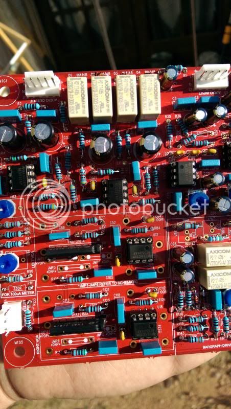
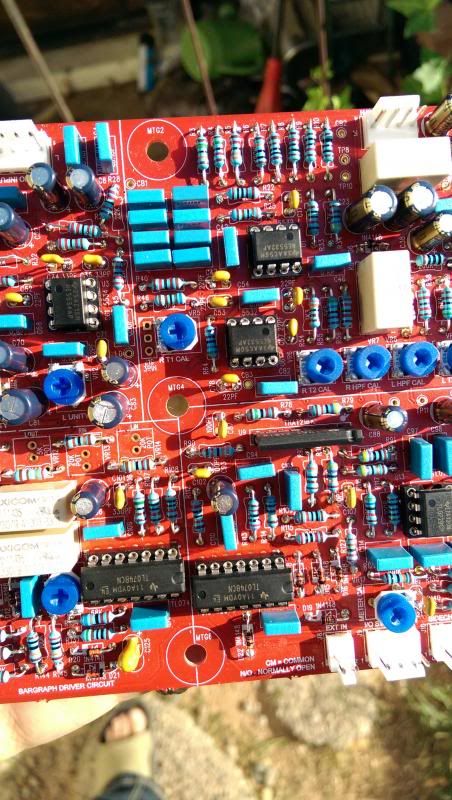
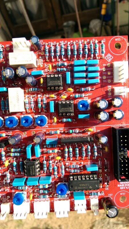
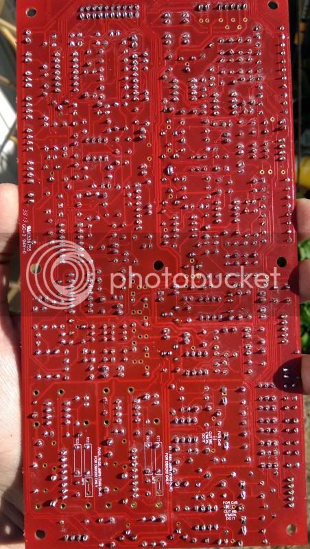
hard to tell in that pic, but do you have the right jumpers jumped in the VCA section?
Similar threads
- Replies
- 0
- Views
- 1K
- Replies
- 98
- Views
- 16K


![Soldering Iron Kit, 120W LED Digital Advanced Solder Iron Soldering Gun kit, 110V Welding Tools, Smart Temperature Control [356℉-932℉], Extra 5pcs Tips, Auto Sleep, Temp Calibration, Orange](https://m.media-amazon.com/images/I/51sFKu9SdeL._SL500_.jpg)


