schematics for langevin 5301

GroupDIY Audio Forum

Help Support GroupDIY Audio Forum:

This site may earn a commission from merchant affiliate links, including eBay, Amazon, and others.
I have several Langevin schematics but nothing on the 5301. All my stuff is preamp & amp. I did find 5 pages of Langevin transformer specifications. I've been trying to scan all my schematics and get them posted.
 
http://cgi.ebay.com/ws/eBayISAPI.dll?ViewItem&category=23793&item=7325451418&rd=1&ssPageName=WDVW is what they look like Wil

Wilebee
 
Don´t know if this is the one, but it´s a compressor using the 6ES8 allright... It´s usually called leveline.

levelineschematic.jpg
 
Where are the A, B, C and D nodes are going to?

Surely the A, B from the cathodes of the AY7 are not going to the A, B in the attack/release time constant network ?!

And, is there a picture, or even a user manual of this online somewhere?

JH.
 
[quote author="rafafredd"]mmm probably just test points to match the tubes?[/quote]

Makes sense. 'Twas the 10k and 100k resistors that confused me - thought they'd have to go somewhere. But then they'r probably just in for protection / isolation of the probes. Never seen this in my ususal circuit reading (synthesizers), but with tubes and their high voltages it certainly makes sense.

JH.
 
[quote author="jhaible"]Where are the A, B, C and D nodes are going to?[/quote]
To A, B, C and D at the bottom right (the pushbuttons). The resistors are there to prevent accidents if somebody pushes more than one button at a time.

Best regards,

Mikkel C. Simonsen
 
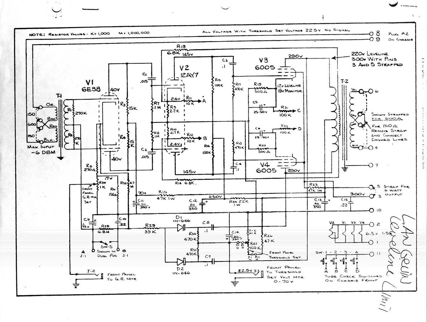
[quote author="mcs"][quote author="jhaible"]Where are the A, B, C and D nodes are going to?[/quote]
To A, B, C and D at the bottom right (the pushbuttons). The resistors are there to prevent accidents if somebody pushes more than one button at a time.

Best regards,

Mikkel C. Simonsen[/quote]

Ok, I see. No slam mode here. :wink:

JH.
 
That was very common with plug-in amplifiers. The output side of those pushbuttons would go to a buss in the console that fed a "tube check" meter. The tapping point for the cathode voltage at each tube--or, in this case, the value of series resistance to limit the current through the meter--would be selected to give a "100%" reading on the meter when the cathode voltage (and therefore the plate current) was at the normal value for a healthy tube. Pushing in the buttons one by one, while reading the tube-check meter, was part of the maintenance technician's daily routine in the studio.
 
[quote author="NewYorkDave"]That was very common with plug-in amplifiers. The output side of those pushbuttons would go to a buss in the console that fed a "tube check" meter. The tapping point for the cathode voltage at each tube--or, in this case, the value of series resistance to limit the current through the meter--would be selected to give a "100%" reading on the meter when the cathode voltage (and therefore the plate current) was at the normal value for a healthy tube. Pushing in the buttons one by one, while reading the tube-check meter, was part of the maintenance technician's daily routine in the studio.[/quote]

Now, that makes even more sense than just protection resistors!
Thanks for explaining it.

JH.
 
Back
Top