Semiconductor based tube-like circuits

GroupDIY Audio Forum

Help Support GroupDIY Audio Forum:

This site may earn a commission from merchant affiliate links, including eBay, Amazon, and others.

Bo Deadly

Well-known member
Joined
Dec 22, 2015
Messages
3,266
Location
New Jersey, USA
I don't want to hijack the tube compressor thread with a conversation about something as elusive as semiconductor based tube-like circuits so I'll post this as a separate thread here.

JohnRoberts said:
There has been a lot of work invested in solid state mimics of tube overload, involving multiple patents.

The approach developed by Peavey marketed as "transtube" was imo pretty successful (but the transtube technology was used in guitar amps, not efx units).
Circuits like transtube (and the one from Crate which is similar I think) are largely just wave shapers which is definitely not at all sufficient. Anyone can overload a clipper, mid-scoop and get Black Sabbath. For subtle distortion, there are other things going on that have to do with dynamics at different frequencies and "blocking distortion" and other things. There are different tube topologies that exhibit very different behavior. Again, refer to Designing Valve Preamps by Blencowe.

I could go into this all day but if there's one thing I've learned about trying to make a circuit that has subtle distortion like a tube, it's that when I think I've definitely figured it out, I most certainly have not.

Part of the problem with trying to figure out how to make a silicon circuit that mimics the subtle distortion of a tube is that one tube stage by itself is not useful for listening tests. There are parts of a complete amplifier that have a large impact on the sound like the output transformer and speaker. You have to build an entire silicon based Fender Twin Reverb, hook it up to a power amp and play it through a speaker (a Jensen P12Q speaker is a brick wall filter at 5kHz) in a room with nice acoustics a few times over some days to really understand how it sounds. That is totally impractical. The alternative is to divide the problem down into parts and study individual sections of the amp in-situ. But again, because the issues have to do with dynamics and at different frequencies, the test procedure would have to involve much more than simple test tones.
 
squarewave said:
I don't want to hijack the tube compressor thread with a conversation about something as elusive as semiconductor based tube-like circuits so I'll post this as a separate thread here.
Circuits like transtube (and the one from Crate which is similar I think) are largely just wave shapers which is definitely not at all sufficient. Anyone can overload a clipper, mid-scoop and get Black Sabbath. For subtle distortion, there are other things going on that have to do with dynamics at different frequencies and "blocking distortion" and other things. There are different tube topologies that exhibit very different behavior. Again, refer to Designing Valve Preamps by Blencowe.
I apologize for the veer. I have no idea what Crate did, but the Peavey approach is patented so if interested search Sondermeyer, and Brown inventors.

I know that there is more going on with dynamic level shifting to mimic the way tubes internal bias gets altered when saturated.

But I repeat this technology is aimed for guitar amps so not subtle. As I have shared before when displayed at a NAMM show set up in a single blind A/B comparison vs a real tube amplifier the majority of players could not tell them apart.

JR
I could go into this all day but if there's one thing I've learned about trying to make a circuit that has subtle distortion like a tube, it's that when I think I've definitely figured it out, I most certainly have not.

Part of the problem with trying to figure out how to make a silicon circuit that mimics the subtle distortion of a tube is that one tube stage by itself is not useful for listening tests. There are parts of a complete amplifier that have a large impact on the sound like the output transformer and speaker. You have to build an entire silicon based Fender Twin Reverb, hook it up to a power amp and play it through a speaker (a Jensen P12Q speaker is a brick wall filter at 5kHz) in a room with nice acoustics a few times over some days to really understand how it sounds. That is totally impractical. The alternative is to divide the problem down into parts and study individual sections of the amp in-situ. But again, because the issues have to do with dynamics and at different frequencies, the test procedure would have to involve much more than simple test tones.
 
Whatever dedication is applied to the endeavour, a SS amp will never sound like a tube amp. Listening to the various DSP emulations, most of the players discern differences, even if they cannot pinpoint excatly how and where.
All analog emulations start with  frequency response, some form of LPF, some compression and a form of soft-clipping, but the more it advances, teh further the goal.
Getting the last bits right takes much more effort than the ground work. That's the well-known cost of the last dB.
Actually many players have accepted this situation and have chosen to play on a SS amp, because sound is an acquired taste, and when balancing pros and cons, it's an overall more practical solution.
 
JohnRoberts said:
I know that there is more going on with dynamic level shifting to mimic the way tubes internal bias gets altered when saturated.
Is this the "transtube" patent?

  https://patents.google.com/patent/US4811401A/en

I don't recall the transtube circuit exactly. It's been a while since I thought about this stuff. Level shifting is only a piece and just because a circuit exhibits level shifting doesn't mean it's got the right dynamics to it. The level shifting is presumably supposed to mimic blocking distortion. But there is a threshold, attack and release defined by the coupling cap, grid resistor, grid stopper and how the grid sinks current.

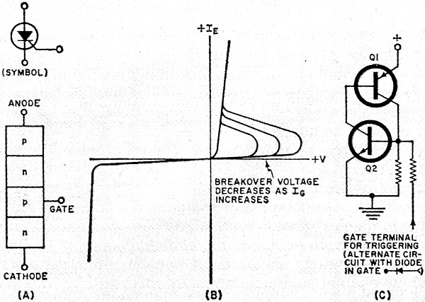
I have a theory that the grid doesn't necessarily start to sink current until it reaches a breakdown voltage but then that voltage drops sort of like a unijunction transistor. The result is a "rhino horn" spike on the leading edge of the clipped waveform but the trailing edge is rounded. That is the sort of thing that would add subtle but audible even order distortion. A circuit to do this that uses conventional transistors might look something like this:

transistors-negative-resistance-dvices-electronics-world-june-1969-10.jpg


But again, this is one little part. The impedance of each terminal of a tube varies greatly under a wide variety of conditions. Personally I just don't think it's possible to mimic something like that with an op amp and a few transistors.
 
That looks like "a" transtube patent but I am pretty sure there was more than one. I vaguely recall a bunch more tricks going on like thresholds for the diode clippers that vary dynamically over time in response to transients and level. I was not involved with the design but shared lab space with Jack Sondermeyers analog group and was friends with all the engineers. I would often chew the fat with them over design problems.

The transtube series had other features like the ability crank down the power where the saturation happened, similar to a tube amp run down at lower mains voltage using a variac.

Another trick was to simulate higher output impedance (like tube amps) to create more cabinet driver interaction... to guild that lily they could selectively tweak the output impedance differently for HF and LF (I vaguely recall amps with two knobs one for LF and HF but that may have been a prototype.) Back in the day these prototype amps would end up at gigs in town, (even at one of my house parties IIRC). Several of the design engineers played in local bands. All the better ones. I recall one bass amp engineer who couldn't play a lick and his amp design reflected that, he didn't make the cut. 

Jack Sondermeyer is now taking the dirt nap (RIP) but James is still vertical, working at Fender over the EVH division, last I heard. There is an engineer who was a junior guitar amp engineer at the time, and still at Peavey now. He surely knows the technology inside out, while I wouldn't ask him to share here and I won't dox him.

JR 

PS: I'm sure Peavey has pretty long list of patents including several of mine, limiting the search to Peavey and Brown and Sondermeyer should result in a shorter list. If you search Peavey and Sondermeyer and Roberts you will find my heatsink patent.   
 
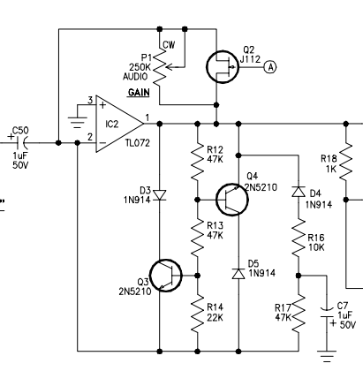
Here's the Crate circuit from the GX120:

CrateGX120.png


Looks like diode thresholds are different and it looks like some kind of biased asym clipper.
 
abbey road d enfer said:
No. It seems the original patent has disappeared. IIRC it was a soft clipper using transistors in the FB loop of an opamp.

https://worldwide.espacenet.com/patent/search?q=pn%3DGB2149954B “distortion circuit”
https://worldwide.espacenet.com/patent/search?q=pn%3DUS4405832A “circuit for distorting an audio signal”
https://worldwide.espacenet.com/patent/search?q=pn%3DTW343021U “Solid state tube compression circuit”
https://worldwide.espacenet.com/patent/search?q=pn%3DUS4290335A “High frequency roll-off circuit”
US4439742A “Circuit for simulating vacuum tube compression in transistor amplifiers”
US4890331A “Specialized amplifier systems for musical instruments”
https://worldwide.espacenet.com/patent/search?q=pn%3DSG34967A1 “Multi-stage solid state amplifier that emulates tube distortion”
US5131044A “Amplifier circuitry with mode compensation and selectable gain and frequency response in pre and post distortion circuits”
https://worldwide.espacenet.com/patent/search?q=pn%3DUS5647004A “Multi-stage solid state amplifier that emulates tube distortion”
https://worldwide.espacenet.com/patent/search?q=pn%3DUS5023915A “Specialized amplifier systems for musical instruments”
https://worldwide.espacenet.com/patent/search?q=pn%3DUS4811401A “Superdistorted amplifier circuitry with normal gain”

The last one in the list was referenced by Abbey. I also included the "solid state tube compression" patent, which is not relevant to this thread. I didn't include any of the power amp patents.
 
I've been going after "Fender Champ in a box" type pedals for years and have dug deeper into JFETs for that purpose than I ever thought I would. I've built 3 or 4 protoboard-based pedals using a couple of different approaches to try to shoehorn something approaching the triode's 3/2 power law from a square law device. The closest I've gotten for the triode section is using tweaks to what the pedal world calls the "Fetzer Valve". But after dozens of tweaks it never gets closer than a rude approximation at 9 volts (you can get closer with 18).

I've looked at Teledyne's approach used with the Fetron back in the 70s for the pentode section, but have never even gotten close to getting that right. Even an actual Teledyne device has significantly different characteristics than the pentodes they were intended to replace. And trying to do the matching Teledyne did with hybrid technology manually has proven a fools errand.

http://www.runoffgroove.com/fetzervalve.html

https://www.casa.co.nz/valves/FETRON_Solid_State_Vacuum_Tube_Replacement.pdf
 
warpie said:
Not exactly on topic but has anyone tried the KORG nutube?

I looked into it back in the day.  It is simply a VFD tube repurposed as a triode, which had already been done before.  The $50 price tag was enough to kill any further curiosity.  I think I uploaded the docs for it here.
 
I don't want to hijack the tube compressor thread with a conversation about something as elusive as semiconductor based tube-like circuits so I'll post this as a separate thread here.


Circuits like transtube (and the one from Crate which is similar I think) are largely just wave shapers which is definitely not at all sufficient. Anyone can overload a clipper, mid-scoop and get Black Sabbath. For subtle distortion, there are other things going on that have to do with dynamics at different frequencies and "blocking distortion" and other things. There are different tube topologies that exhibit very different behavior. Again, refer to Designing Valve Preamps by Blencowe.

I could go into this all day but if there's one thing I've learned about trying to make a circuit that has subtle distortion like a tube, it's that when I think I've definitely figured it out, I most certainly have not.

Part of the problem with trying to figure out how to make a silicon circuit that mimics the subtle distortion of a tube is that one tube stage by itself is not useful for listening tests. There are parts of a complete amplifier that have a large impact on the sound like the output transformer and speaker. You have to build an entire silicon based Fender Twin Reverb, hook it up to a power amp and play it through a speaker (a Jensen P12Q speaker is a brick wall filter at 5kHz) in a room with nice acoustics a few times over some days to really understand how it sounds. That is totally impractical. The alternative is to divide the problem down into parts and study individual sections of the amp in-situ. But again, because the issues have to do with dynamics and at different frequencies, the test procedure would have to involve much more than simple test tones.
Marshall 3210, 3005/5095 as well as all the other solid state amplifiers released during the JCM800 series era used Darling transistor tooography to create tube like reactions in these amplifiers.
 
Some of the more convincing stuff Ive seen has been done by Patrick Quilter and Quilter amps. He's talked about some of the stuff over the years but theres some interesting stuff in his patents too. Sag is a really important factor, higher output impedance like John was saying and emulating the negative feedback, bias shifting and soft clipping. He's made some pretty convincing stuff with class d power amps and I have been wanting to play around more with some of his ideas to make lighter hybrid amps. I still feel like it lacks some of the harmonic information tubes offer though. I could never really get into the transtube stuff.
 
Just my 2cents: The transition to distortion region, I think, is the hardest to simulate well. The high gain stuff is easier, at least based on the circuits I have built.
 
Back
Top