simple passive monitor switcher/attenuator

GroupDIY Audio Forum

Help Support GroupDIY Audio Forum:

This site may earn a commission from merchant affiliate links, including eBay, Amazon, and others.
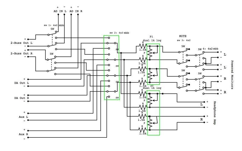
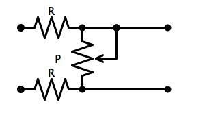
the way I understand it, with a u-pad (like the ones above) the output impedance of the pad (what your monitors will see) is equal to the value of R shunt - in this case, the pot. So with a 1k pot, the output impedance of the pad will always be somewhere in between 0 (full attenuation) and 1k (full volume). The input impedance of the pad (what your source will see) is equal to R series (in the JLM schemo, 1k + 1k = 2k) plus R shunt. So in the JLM schemo, the input impedance of the pad will always be somewhere in between 2k (full attenuation) and 3k (full volume).

i think this is right, but i just learned it over the past couple of days at http://www.uneeda-audio.com/pads/ - hopefully someone will correct me if i dont understand it right - Ben
 
I think the Uneeda audio drawings assume a floating circuit. Electronically balanced inputs and outputs are ground referenced. In the U pad it looks like depending on where the wiper is there would be unequal impedance to ground for each leg except when it is in the center.

I of course could be wrong.
 
sorry if I'm being dense, but wouldn't the pot just act as a variable R shunt like this?
variableupad.jpg

-Ben
 
It is acting as a variable shunt between legs of a balanced line not between line and ground. Both the + and - leg should have equal impedance to ground. That is generally what defines a balanced line. A fixed U pad would retain this relationship. I don't think this variable would. That is my question. And if not does it matter?

I think the down side to this method is that the CMRR of the next stage would be compromised. Unless the circuit is floating.
 
Gold said:
It is acting as a variable shunt between legs of a balanced line not between line and ground. Both the + and - leg should have equal impedance to ground. That is generally what defines a balanced line. A fixed U pad would retain this relationship. I don't think this variable would. That is my question. And if not does it matter?

I think the down side to this method is that the CMRR of the next stage would be compromised. Unless the circuit is floating.

There is no problem with the variable U-pad considering the balance in general. BUT the pad it self lets common mode crap go through with full level while attenuating the audio signal. I don't think this will be a problem here, if you keep your lines short. It does not hurt the CMRR of the receiving device, so basically if you have perfect CMRR in the speakers you might get away with quite long lines. (but you never have)

The 1k impedances are a fine choice in my opinion. The maximum output impedance will be less than 1k, by the way.

I've had hum problems when using 60dB attenuating and testing mic pre-amps. Then a ground referencing pad would have been handy. But that is another story. I use these pads in many of my line level equipment without trouble.

Furthermore it does not matter whether you have transformer floating or electrically balanced outputs/inputs, but they _have to be_ balanced.

I don't know where you will find your pot, not the easiest component to source if you want to retain channel balance. (I'd go for 2-deck rotary switch for many reasons.)

I hope this helps.

 
Hi guys, I think this is the simplest solution, quality- and ergonomics-wise.

http://www.groupdiy.com/index.php?topic=30914
http://www.groupdiy.com/index.php?topic=32157.0
 
Jonte Knif said:
There is no problem with the variable U-pad considering the balance in general. BUT the pad it self lets common mode crap go through with full level while attenuating the audio signal. I don't think this will be a problem here, if you keep your lines short. It does not hurt the CMRR of the receiving device, so basically if you have perfect CMRR in the speakers you might get away with quite long lines. (but you never have)

The 1k impedances are a fine choice in my opinion. The maximum output impedance will be less than 1k, by the way.

I've had hum problems when using 60dB attenuating and testing mic pre-amps. Then a ground referencing pad would have been handy. But that is another story. I use these pads in many of my line level equipment without trouble.

Furthermore it does not matter whether you have transformer floating or electrically balanced outputs/inputs, but they _have to be_ balanced.

I don't know where you will find your pot, not the easiest component to source if you want to retain channel balance. (I'd go for 2-deck rotary switch for many reasons.)

I hope this helps.

Thanks - This helps a lot. The problem with the 1k pot and 2k R series (as in the JLM schematic) as i see it it, is that the input impedance of the pad is only 3k at most - and if you are running a 600 ohm source (like my 2-buss) that seems pretty low, right? you could change R-series to 6k, but then you would have ~16.5 attenuation at max vol. This might be ok for me, however because I run my monitor at half volume anyway - I could just turn them up. But with what you just told me about a u pad not attenuating common mode noise, this might be bad. I could do a 2k pot - which would be great, but i would never find a dual gang 2k log pot.

The rotary switch seems like a good idea, just expensive - especially for something with 23 steps. and it almost seems like if I'm going to go that route, I should just get a six deck switch and make a bridged-t attenuator and not have to worry about these impedance issues. But this gets really expensive.

Igor said:
Hi guys, I think this is the simplest solution, quality- and ergonomics-wise.

http://www.groupdiy.com/index.php?topic=30914
http://www.groupdiy.com/index.php?topic=32157.0

Yes, the simplest, best sounding , most functional, and best looking solution to be sure. I just can't afford it unfortunately, not that i haven't spent time trying to convince myself that I could.

-Ben
 
what about using THAT vca's as an atennuator?


Igor your stuff always looks nice, no doubt about it!
Just way to expensive and sometimes big to small project studios...
Those times around too economy its scary!!

Take care.
 
HI
great job.....!
do you think can be a wrong idea add a vu meter or a meter led
for view gain in and gain out?
(starting from a standard +4db professional gain range , i think also a switch to -10db input cannot be a nightmare)

difficult project?

cheers to all
6T9R
 
if you are running a 600 ohm source (like my 2-buss) that seems pretty low, right?

I don't think so, but can not be sure because I don't know the equipment you are using. Output impedance and drive capability are two different things. Remember that in the old days gear had 600 Ohms outputs AND inputs. And no problems. On the other hand some modern IC crap (and even tube crap too, well known brands) which has low output impedance (50-100 Ohms) will run into problems when connected to 600 Ohms. (and rarely even 2k Ohms)

About the CMRR-stuff. I would not give up yet. I you have time, just make a fixed U-pad to an XLR cable and try! Then you'll know.

That Igor's kit is really something!
 
Why not just use a quad gang log pot in the normal way? Either 5k or 10k.

Makes sense, perhaps not 10k (quite high output impedance at maximum of 2,5k, top end loss possible) , but 5k or 2k.
Do you have a source in mind? I'd be interested if these are available from quality manufacturers, especially in 2k or 1k Ohms. Kind of special products, aren't those? Made to order mostly. Honestly I don't know :)


Gold said:
Why not just use a quad gang log pot in the normal way? Either 5k or 10k.

hey Paul - what do you mean by the normal way. I don't know much about different styles of volume controls. I've only been reading on this stuff for the last couple of weeks - I'm sure I'm looking over something obvious. - Ben
 
By the normal way I mean the the input is at the top of the track, the bottom of the track is connected to ground and the output is the wiper. The input impedance is constant and the output impedance varies from the value of the pot at no attenuation to zero at full attenuation. You would need a four gang pot to do stereo balanced. I haven't looked around for a source. Alps? TKD?
 
Gold said:
By the normal way I mean the the input is at the top of the track, the bottom of the track is connected to ground and the output is the wiper. The input impedance is constant and the output impedance varies from the value of the pot at no attenuation to zero at full attenuation. You would need a four gang pot to do stereo balanced. I haven't looked around for a source. Alps? TKD?

I'm afraid that's not the case. With a voltage divider, the output impedance is equal to the value of the two resistance halves in parallel. Therefore, it is highest at the midpoint, where Zout is 1/4 * Zin. That is, for a 10K pot, max output impedance is 2.5k, when the wiper is at the 5k position, or -6db.

James
 
jamesfei said:
I'm afraid that's not the case.

Okay. If the wiper is at the top of the track wouldn't that be 10k and 0 in parallel giving an output impedance of 10k? Granted my math is pretty bad.
 
Don't forget the impedance of the source driving the pot. In real life it is not zero and certainly not infinite :) At full volume the output impedance is a bit lower than source, because there is the pot in parallel. So, never the pot value. At some point (not exactly mid point) the impedance reaches maximum which is close to 1/4 if the source is low compared to the pot. Simple as that. (If the source and pot happened to have the same impedances, then the maximum Z out is at full volume. Rarely the case)
 
So doesn't http://www.goldpt.com/ fit the bill. In my budget anyway although I am using a buffer circuit as my amp doesn't like the direct route. When  I do my powered monitors I can do away with the buffer but  I am running passive monitors and the new ones
about to be built are also passive.
 
I think i'll DIY all the switching...as well as my headphone amp (2 sets) and for attenuation this is my solution:
300_iNano_2_01.jpg

;D ;D ;D ;D
 
I came up with a couple of ideas for boxes
here's the balanced version:
monitorcontrollerbalanced314-1.jpg

The balanced version has a ~12db loss at full volume for both the headphone amp out and main monitor out. Both variable u-pads (1 for monitor volume control and one for headphone volume control) have a 4k input impedance (at full volume) and they are connected in parallel so my console output sees 2k. I could use non-variable bridged-t pad for the headphone amp out with a 10k input impedance and ~18db loss - then my console outputs would see about 3k. (I'm afraid my console outputs will overdrive my headphone amp input if they are not padded down.)
and the unbalanced version:
monitorcontrollerunbalanced314-1.jpg

I'm leaning toward the unbalanced version - partially because it is a lot easier to find nice dual 10k pots than it is to find nice dual 1k pots.
If anyone finds time to critique these circuits or offer their opinion that would be awesome. -thanks, Ben
 
Back
Top