You are using an out of date browser. It may not display this or other websites correctly.
You should upgrade or use an alternative browser.
You should upgrade or use an alternative browser.
SSL 4000 EQ
- Thread starter Dubka
- Start date
Help Support GroupDIY Audio Forum:
This site may earn a commission from merchant affiliate
links, including eBay, Amazon, and others.
Vac11
Well-known member
Some progress...

Question:
1) For 4k75 resistors (only) I used 600mW instead of 250mW ... Is this a problem?
Here is a 23p switch for gain as a replacement for 25k lin center tap pot:

Thanks for gerbers to Signalflow ...
Vac11

Question:
1) For 4k75 resistors (only) I used 600mW instead of 250mW ... Is this a problem?
Here is a 23p switch for gain as a replacement for 25k lin center tap pot:

Thanks for gerbers to Signalflow ...
Vac11
Hi Vac11,
great work you are doing. Congrats
1) For 4k75 resistors (only) I used 600mW instead of 250mW ... Is this a problem?
I dont see any problem with that
great work you are doing. Congrats
1) For 4k75 resistors (only) I used 600mW instead of 250mW ... Is this a problem?
I dont see any problem with that
Vac11
Well-known member
Thanks Whoops!!
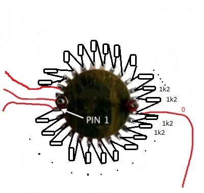
OK, here is a frequency switch resistors chain (E24)... It should be a substitute for 50k dual gang antilog pot ... Not tested yet...
I will use 2 pole 24p Ural tone switch... Resistor chain is the same for first pole and second pole of switch.

OK, here is a frequency switch resistors chain (E24)... It should be a substitute for 50k dual gang antilog pot ... Not tested yet...
I will use 2 pole 24p Ural tone switch... Resistor chain is the same for first pole and second pole of switch.

signalflow said:So long story short it's working and sounds pretty damn good. I'm gonna play around with the caps in the HF section, got some styrene caps to try out, the polyester caps seem kinda weak.
Hi Casey,
I'm putting together a mouser order for a pair of boards. Did you ever play around with the HF section caps? If so, anything you came across that sounded better than polyester?
Thanks!
Keith
signalflow
Well-known member
Krcwell said:Did you ever play around with the HF section caps?
My prototype had different caps than the version I released and I never took the opportunity to build a revised version. So, in this case it's just play with it until you find what you like.
-Casey
Vac11
Well-known member
I didn´t.
I´m just waiting for PSU PCB and more time for DIY
11 position Lorlin rotary switches for +- gain are ready.... I also have wired all needed potenciometers (for Q and frequency)...
M.
I´m just waiting for PSU PCB and more time for DIY
11 position Lorlin rotary switches for +- gain are ready.... I also have wired all needed potenciometers (for Q and frequency)...
M.
Vac11
Well-known member
Ok, I have a few news.
1) EQ was alive on the first run, no smoke.
2) EQ pass audio without any artifacts.
3) Center position on 25k lin rotary switches with 2k49 works very well (flat frequency response in "0" position)
4) Small yellow cheap chinese relay clics and switches correctly...
Some troubles:
1) Still I could not proper calibrate Q. Q is very much wide (on 2 last pics is Q pot ccw and cw with full gain on the switch). I fail to calibrate it to be narrower...500R trimmer does not help me too.
2) +- Gain switch on Highs doesnt raises the volume to the same level as switch for bass (only +- 6-7dB)
Any ideas?
Some pics:


Vac11
Well-known member
Bump!
Second board has exactly same problem with Q and gain on Hi. I checked resistors and caps and they look correct.... :-(
Edit:
I solved dysfunctional Q ... It looks like a small bug on PCB layout. When I joined backwards first and third leg on the first deck 10K log potentiometer into the holes on the PCB, everything works as it should .... Q works correctly now. Please keep this in mind and check it out.
82E02 EQ Calibration:
"Set the Oscillator frequency to 3kHz, switch the EQ section in with full HMF boost, and narrow 'Q'. All other gain controls should be set to their detent positions (flat). Adjust the frequency control until the output level peaks. At this frequency and 'Q' setting the Boost/Cut control should give +15dB of gain. This should be set with the preset control marked 'HMF Q'. Repeat the above at 1kHz for the LMF section using 'LMF Q'. There is no adjustment for the HF or LF sections."
Attachments
Vac11
Well-known member
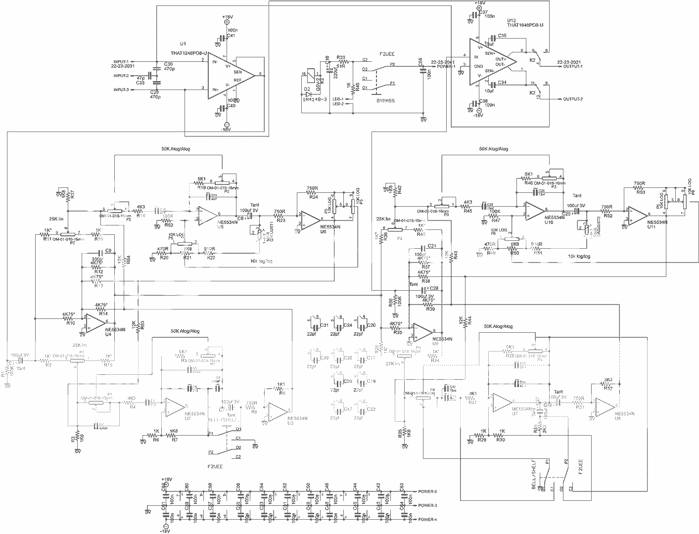
I solved lower gain on HI. In BOM is R9 marked as 1K5. There is 7K5 for this position in original schematic. I swaped this resistors and HI are working properly now = +-15dB.  EQ sounds great to my ears. Especially on drums. Thanks to Signalflow.

Other curve - both Q pot on narrow side max, HI and LOW shelf + 3-4 dB:

R9=7K5


Other curve - both Q pot on narrow side max, HI and LOW shelf + 3-4 dB:

R9=7K5

signalflow
Well-known member
That's great! And good eyes too, on my copy it really does look like a 1 and not a 7. Good luck with it!
-Casey
-Casey
bruno2000
Well-known member
signalflow said:
-Casey
In your schematic, P5 (just to the right of U6) shows 2 sections of the 10k log pot in parallel with each other. In the original schematic from SSL, there is only one section. Is this something that you found that improves the performance?
Thanks!
Best,
Bruno2000
signalflow
Well-known member
Brunno,
that section you are referring to was made to be able to use either alpha or omeg pots. Since the spacing between decks are not standard between the two. They are not meant to be connected to a 3 deck pot.
-Casey
that section you are referring to was made to be able to use either alpha or omeg pots. Since the spacing between decks are not standard between the two. They are not meant to be connected to a 3 deck pot.
-Casey
bruno2000
Well-known member
signalflow said:Brunno,
that section you are referring to was made to be able to use either alpha or omeg pots. Since the spacing between decks are not standard between the two. They are not meant to be connected to a 3 deck pot.
-Casey
Thank you!
Best,
Bruno2000
signalflow said:Here are the gerbers .
There are a few for the taking. Though not all have been tested, Nor are they supported. Schematics and a board image is included in the zipped folders.
https://drive.google.com/folderview?id=0B5TzR7Ho7CD9fnVRY2hOSU9CaGs0anAwdVdVMmJKOXNUX1VOcHg4c1hqalkwOWtFbXFHV1U&usp=sharing
Is it just me or are the gerbers for the SSL EQ disappeared? On this link i only found the gerbers for the 4k preamp. Could you re-upload it please?
Thanks in advance.
Kind regards,
Wouter
orangechili
Well-known member
I don't see them in there either? I'm looking at doing some of these too. Does anyone have them to upload possibly?
3nity
Well-known member
Someone heres is offfering the boards?
Id like to build a pair.
Thanks.
Id like to build a pair.
Thanks.
Similar threads
- Replies
- 16
- Views
- 1K


