SSL 4000 EQ

GroupDIY Audio Forum

Help Support GroupDIY Audio Forum:

This site may earn a commission from merchant affiliate links, including eBay, Amazon, and others.
3nity said:
Someone heres is offfering the boards?
Id like to build a pair.
Thanks.

Vac11 still has a pair of his prototype PCBs for sale at the Black Market, see http://groupdiy.com/index.php?topic=62824.0
 
I just begun to build this project (using signalflow's boards that I ordered from Vac11. Many thanks to both of them!). The stuffing order is a bit weird, since my resistors won't arrive until next week. :)

I haven't yet finalized my plans with all of the pots, but I might use ordinary 25k pots without the center dents for the gains, since they are cheaper and easier to find.

To this date I've mainly worked on stompboxes and 500 series modules, and that's why I'm pretty ignorant when it comes to power supplies. Would anyone have any suggestions on what kind of PSU to choose for this project?
 

Attachments

  • IMG_1326.JPG
    IMG_1326.JPG
    1 MB
Hi Lagrange,
try ACDC PSU pcb from JLMAudio.com... There is also build thread with lot of useful info on their web...You need +-18V and +12V for bypass relay.

M.
 
Vac11 said:
Hi Lagrange,
try ACDC PSU pcb from JLMAudio.com... There is also build thread with lot of useful info on their web...You need +-18V and +12V for bypass relay.

Thanks for the tip!
I will look into the JLM Audio's products.
 
Thank you so much for uploading these. And of course thanks to signalflow for making them.

Kind regards,

Wouter

Whoops said:
Here they are,
I cant attach a ZIP file,
so I compressed the gerbers and changed the Extension from ZIP to PDF.
Download the file and then change the extension back to ZIP and extract the files from the ZIP
 
Hi there!
I have a simple, stupid question!
No tranny on SSL? 
I Know, there's cheap ect, but in a Sonic characters..?
 
If someone is still looking for PCBs, I thought I'd mention that Vac11 is selling them again in his BM thread here:

http://groupdiy.com/index.php?topic=62824.0
 
Hi!

I've made some progress with the project, thanks to the helpful posts in this thread. I built the JLM AC/DC PSU as suggested by Vac11, and it's working very well. One of my EQ channels seems to be working flawlessly, but the other one has a strange fault that the negative power rail shorts to ground, and the channel obviously does not function. This problem is strange only because I could swear that it was working quite well yesterday!

Since the negative power rail mainly connects to the 4th pins of the ICs, that in turn are connected to ground via the SMT caps on the downside of the PCB, the most likely cause is a solder brigde caused by a bad sufrace mount soldering. Still, I couldn't find any such places with visual inspection or with my multimeter (the resistance between 0 and V- is around 3,5 Ohms everywhere, and by my reasoning it should be at least a bit lower near the solder bridge, but I couldn't find any place where this would happen). I've been debugging this for a couple of hours, but I haven't yet gone to taking out the SMT caps, which might be quite tricky.

Would anyone here have any idea if this problem could be caused by anything else, or how to find the root cause of the problem (whether it's a solder bridge or something else)? I would very much appreciate any comments.  :)

 
Hi!

Just to update a little bit: My problem in one of the channels seemed to be that one of the SMD caps had broken down and turned into a conductor, and that caused the short. This was C38, connected to the output IC THAT 1646, between ground and the negative -18v rail.

I was lucky enough so that this broken cap was the second one (out of the 13 possible ones!) that I pulled out. I replaced it with a functioning cap. I put everything together and turned the channel on, but after 20 seconds the output died down, and when I checked, the -18v rail was again shorted to ground. I didn't check yet, but I'm guessing probably the same cap has broken down. Would anyone have an idea what might cause this? A short somewhere else? The cap should be rated 50V, which is more than it should need to handle.
EDIT: Actually the second time around it was another SMT cap, C64, that had broken down. This one is between -18v and ground right next to the PSU input on the board.
 
- Does anyone have a current source for the pots and relays?

- I see JLM has the AC/DC power supply V.4 - it's a 3 rail, is that the right one?

I also wouldn't mind snagging an .fpd file if anyone made one, if not I will make one and upload it :)

Many thanks to Vac11 for selling me a few of these. They will make great companions to my SSL 611DYN!!  8)
 
I used these cheap chinese relays:
http://www.ebay.com/itm/DC-12V-Coil-DPDT-8-Pin-2NO-2NC-Mini-Power-Relays-PCB-Type-HK19F-/182004423868?hash=item2a604f1cbc:g:lbMAAOxyoA1RUZcj
Works great, but remember it is not the best quality relay...
 
Ok, so I started working on a front panel in Front Panel Express. I've got the spacing down, but I am not sure about height including PCB, standoffs, and the pots once they are mounted. Does anyone have a completed build and can contribute to the .fpd regarding measurements? I will upload the FPD when it's complete.

- I need spacing from the bottom of the faceplate to the center of the 20mm pots.
- Spacing for the pots that aren't on the pcb.

If anyone could contribute, it would much appreciated! I am pretty handy with FPE but I am not an engineer by any means!
 
Hi Justin!

I think the pots should be 16mm instead of 20mm.
The ACDC PSU is the correct one indeed.

You should also note that if you like, you can skip the relay and the bypass switch completely (I didn't think about this until I had already assembled the PCB). For example, if you only plan to use it as an external device from a DAW, you can bypass from there. But of course, for many other purposes the bypass switch is convenient. :)
But if you do skip the relay, then you won't need the +12V rail in the PSU either, and you have more options in that area too.
And if I'm missing something here, everyone please feel free to correct me! :)

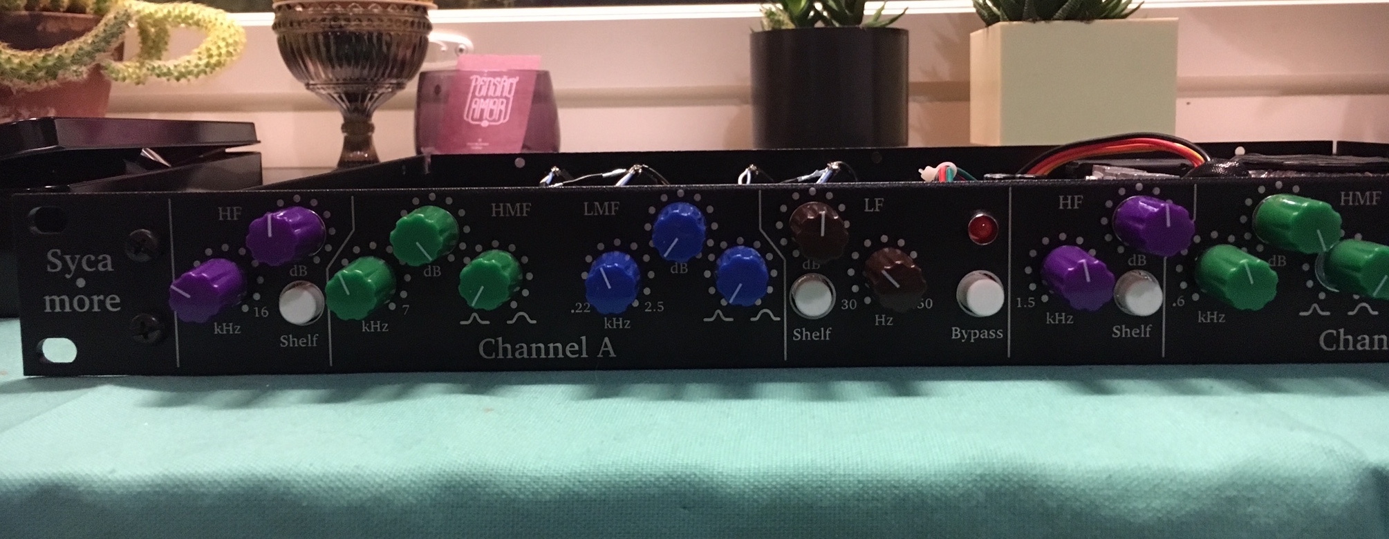
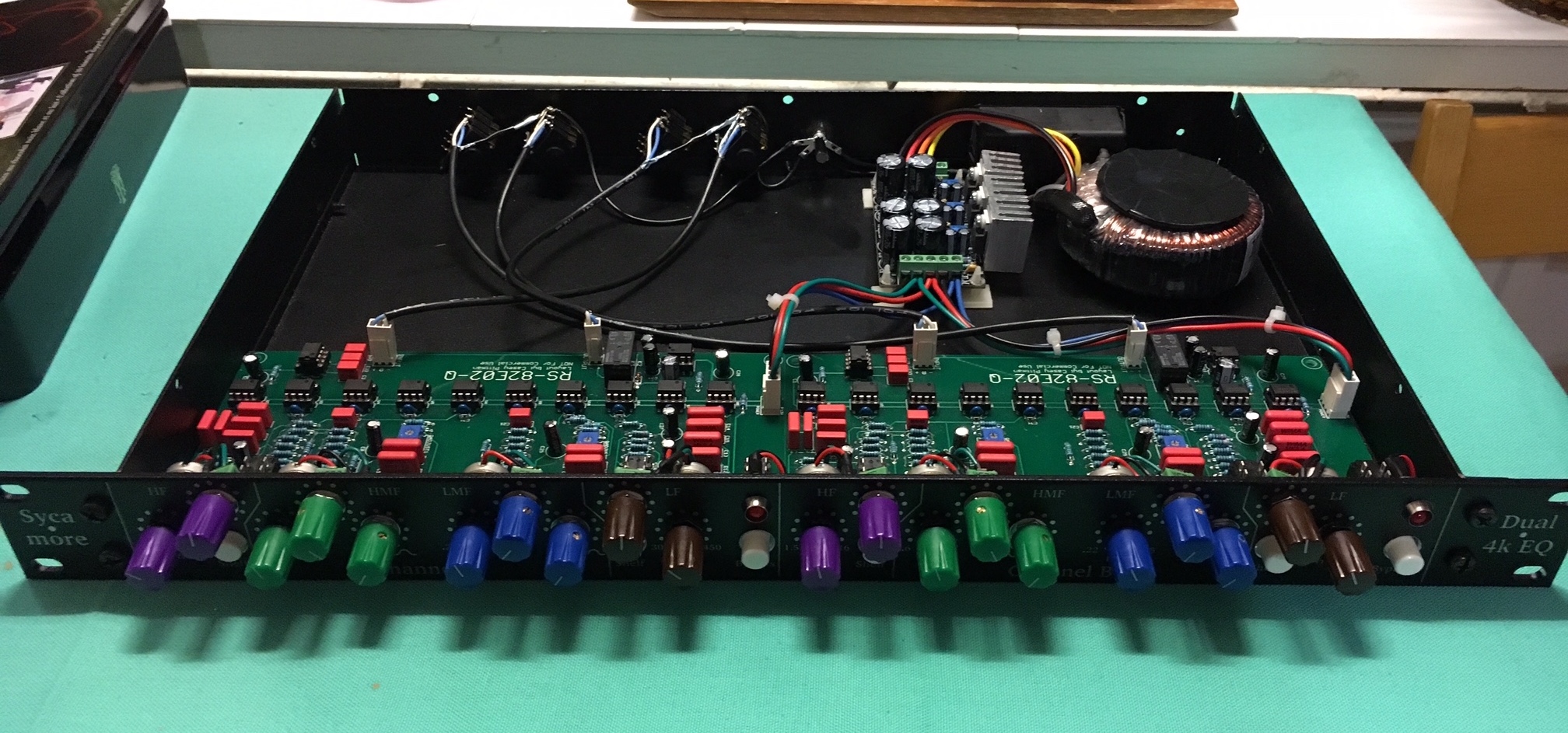
I finished my unit, though I haven't had a chance to test it in practice yet, I've only been running sweeps through it so far.  Here are a couple of pictures:

LJwFzhS.jpg


WZEfk8J.jpg


I also have a couple of comments I thought of that didn't occur to me beforehand:

For the frequency pots I used the Omeg pots from Audio Maintenance. Those were a bit expensive compared to other parts, but the reverse log tapers are not that common. I think it would also be possible to make your own rev log taper by adding a resistor in parallel with a linear pot. The principle is explained in http://www.geofex.com/article_folders/potsecrets/potscret.htm but the values of the pot and the resistor need to be figured out carefully.
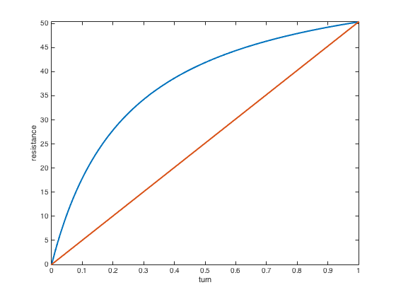
I did some calculations, and for me it seemed that you could end up pretty close to a 50k reverse log taper by taking a 250k linear pot and connecting a 63k resistor between 1st and 3rd legs (of course for a dual pot you would of course do this for both of the channels). The attached picture describes the (theoretical) shape of the resistance as a function of the turn of the pot. Going to 68k gives the pot a sligthly higher total resistance (around 53k), and 56k lower (around 46k), but both of those would probably be ok too. I didn't try this out in practice, but if someone does, let me know how it works out! Since pots are for frequencies, the actual precise values should not matter that much, as long as the shape is similar and the same for different channels. Also I think the DIY reverse log pot should be within the usual tolerances of pots.

CGJXuTz.png


That being said, the Omeg pots I used are really nice. However, for choosing the knobs you should note that the shafts of the 16mm pots in this project are plastic and small. I went with regular 6mm shaft pots, but I needed to add some padding in between (I used pieces of rubber from a guitar cable) and the end result is a bit "wobbly".

For the gain pots I used those smaller pots (those with green or blue backs and so on) to make it all fit in 1U, but I couldn't find any of those with center detent. If you are building in 2U, or only one channel in 1U, one very good option is the stepped gain that Vac11 used.
 
Here's the faceplate that I designed for my unit, it's in Inkscape SVG format. You are free to modify it for your own use (not for commercial purposes!). I only ask that if you improve it in a significant way, you could share your version here on the forum as well for the benefit of others. :)

This is not something that can be readily sent for manufacturing! Use it carefully, and verify with your own measurements, or use the dimensions as a basis for your own design. I used the design for an Adam Hall 1U case I got from Thomann, and things worked out fine, though the space is definitely limited for 2 channels in 1U space. For my own unit I used a laser to engrave the labeling to the faceplate and then I drilled the holes manually. It worked really well for me!
 
Nice piece of gear, congrats!!! Did you find out where was the problem with one of your chanels?
Thanks for sharing your experiences...

M.
 
Vac11 said:
Nice peace of gear, congrats!!! Did you find out where was the problem with one of your chanels?
Thanks for sharing your experiences...

M.

Thanks!

I think the problem was that the SMD caps just gave out for some reason. I ended up replacing all of them in that channel and it's been working since (though I haven't yet had a chance to use it for longer periods). It might have been my soldering, or perhaps I used too much solder flux that acted as a conductor etc.
 
Lagrange said:
Here's the faceplate that I designed for my unit, it's in Inkscape SVG format. You are free to modify it for your own use (not for commercial purposes!). I only ask that if you improve it in a significant way, you could share your version here on the forum as well for the benefit of others. :)

This is not something that can be readily sent for manufacturing! Use it carefully, and verify with your own measurements, or use the dimensions as a basis for your own design. I used the design for an Adam Hall 1U case I got from Thomann, and things worked out fine, though the space is definitely limited for 2 channels in 1U space. For my own unit I used a laser to engrave the labeling to the faceplate and then I drilled the holes manually. It worked really well for me!

WOW! Thank you so much for posting, Lagrange! Your build looks legendary  8)

So the pots are 16mm?
- I am confused as to which pots (values, concentric, log) I actually need to buy, there seems to be a few different answers throughout the thread. Can someone please clarify? Some of the ones stated in the thread/BOM don't seem to be in stock at AML.

Forgive my ignorance, I am still pretty new to DIY. I would like to order the pots as soon as possible in case they disappear forever, if they haven't already  :eek:

I will probably rack mine in a 1U case as well just to keep things clean and utilize rack space to the fullest. I was planning on using the rectangle switches and knobs from SSL - or possibly seeing what Don-Audio has to offer. I'm going to build the .fpd file so that something can be easily modified and manufactured for everyone.
 
Concentric Omeg potentiometers from AML are no longer available. I asked Colin. But! you can order these directly from Omeg. You need dual concentric pot which consists of dual 50k reverse log (or "C") and singel 25K linear (or "B") in inner shaft with center "zero" position. 16mm footprint. These are for frequency sweep (dual 50KC) and for gain adjust (25KB).

For Q adjust is sufficient standard dual tape 10K logarithmic (or "A") potentiometer.
 
Vac11 said:
Concentric Omeg potentiometers from AML are no longer available. I asked Colin. But! you can order these directly from Omeg. You need dual concentric pot which consists of dual 50k reverse log (or "C") and singel 25K linear (or "B") in inner shaft with center "zero" position. 16mm footprint. These are for frequency sweep (dual 50KC) and for gain adjust (25KB).

For Q adjust is sufficient standard dual tape 10K logarithmic (or "A") potentiometer.

I appreciate your responses. I am, however, even more confused as I can't see anything resembling a 50k rev log pot on the BOM that was posted.

Potentiometers
47K/47K/22K                      P1-P4            Triple Gang Concentric
10K                                            P5 P6              Dual Gang Log
500ohm 2                              Q Adjust trimmer 1 & 2
47K                                            P1-P4              Freq Dual Gang Rev Log optional
25K 4                                        P1-P4              Gain Center Dent linear optional

So for P1 - P4 can I use either triple gang concentric or dual gang log?
I still can't seem to make sense of what pots I need to order for this build. I don't understand the "optional" pots as no one seemed to mention them before.
 
Vac11 said:
Concentric Omeg potentiometers from AML are no longer available. I asked Colin. But! you can order these directly from Omeg. You need dual concentric pot which consists of dual 50k reverse log (or "C") and singel 25K linear (or "B") in inner shaft with center "zero" position. 16mm footprint. These are for frequency sweep (dual 50KC) and for gain adjust (25KB).

For Q adjust is sufficient standard dual tape 10K logarithmic (or "A") potentiometer.

Ok, I think I am making sense of this. You are speaking of the triple gang pots to order from Omeg, yes? So this is what I would order on Omeg?

FRONT - 47k - Law C
MIDDLE - 47K - Law C
REAR - 22k - Law B
 

Latest posts

Back
Top