Lowfreq
Well-known member
I'll take 3nity's boards if he's not taking them. Let me know if thats all good, and I'll send the paypal through. 


Indecline said:I saw that Casey planned on offering filter boards sometime in the future
Indecline said:One more question: On the schematic the 100uf caps are labeled Tant, should these be tantalum capacitors?
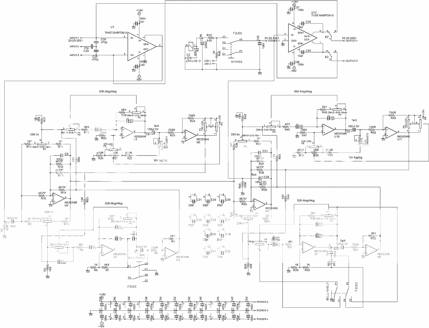
signalflow said:And here is the schematic with values for the filter board.
This is strait from the original schematic. I have not tested this since I just did it last night. So if something isn't quite right, you have been warned.
-Casey
Indecline said:signalflow said:And here is the schematic with values for the filter board.
This is strait from the original schematic. I have not tested this since I just did it last night. So if something isn't quite right, you have been warned.
-Casey
I dumped it into spice to check it out. The high pass was acting fishy and not going past 80hz. Checked it against the original and it seems that C23 was left out ;D Popped into spice and bingo! Up to 330hz, low pass filter checked out down to 3.1khz inside computer land.
Enter your email address to join:


