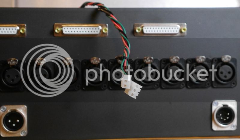
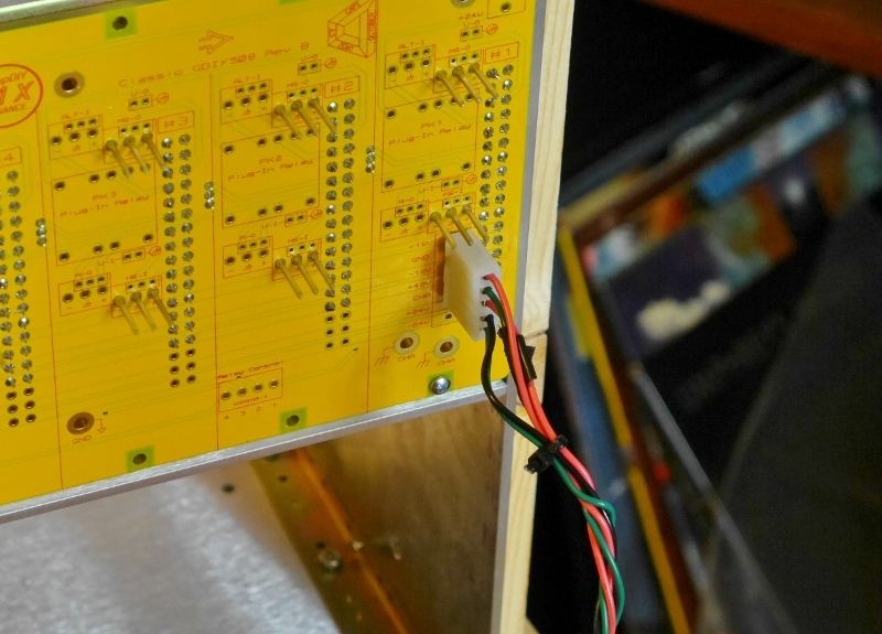
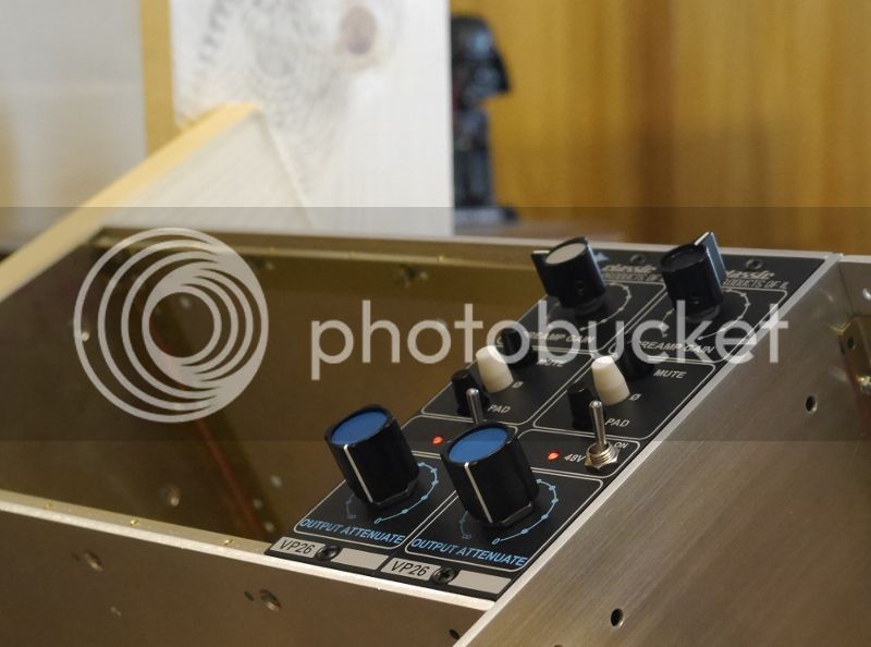
Starting a modular console - CAPI/GDIY 508 rack build

GroupDIY Audio Forum

Help Support GroupDIY Audio Forum:

This site may earn a commission from merchant affiliate links, including eBay, Amazon, and others.

Krcwell

Well-known member
Joined
May 11, 2014
Messages
152
Location
US
Hello all,

I've been lurking for quite some time, soaking up the vast amount of knowledge that this board has to offer.  So before I begin, I thank all of you very much.

I've been running a somewhat respectable recording studio out of my house for pretty much a decade, mainly focused on drum tracking.  My first intro to DIY was acoustic treatment, and I found the learning, planning, and constructing process very rewarding.  Electronic circuitry has always intimidated me, but about a year ago I stumbled across Classic API's website (which led me here), and the thought of DIY gear intrigued me.  My API 3124 is what made me learn mic placement; there's one knob, and if it doesn't sound awesome, then it isn't the preamps fault: go fix your placement.  I have a love for API gear, and wanted to build my own.

I've always lusted after an API console, having been afforded the opportunity to play with the first 1608 delivered at IV Labs in Chicago.  Realizing a full console is a long way off, I need to start somewhere.  Wanting to get into the 500 series format, there's the obvious choice of the GDIY 511 rack, an all in one package that even a noob such as myself could assemble, thanks to Chunger's build threads.  But then there's Jeff's 500 series modular console monster thread; after reading through that several dozen times, I concluded the Classic API/GDIY 508 rack system was where I would start, even if I would have to actually figure out I/O connections and some sort of support structure for it on my own.

The next couple posts will be photo logs of the Classic API single 508 rack bucket and backplane build, followed by next steps.  I figured photodocumenting the build would maybe help other noobs out (a la Chunger's great work) and hopefully allow people to red flag anything I'm doing wrong... like I said, still a noob. 

Also, I'm going to have tons of questions.  :)

Keith
 
Step 1: Classic API single bucket 508 rack build

Gotta start somewhere.

I ordered the single bucket 508 rack kit from Classic API, which came with everything except headers for I/O connections on the backplane.  I bought the .156 I/O header kit along with it, which will be covered in the backplane build.

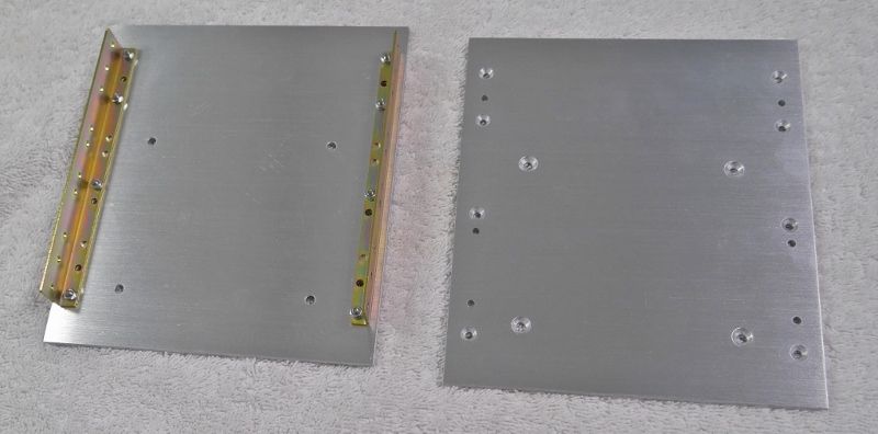
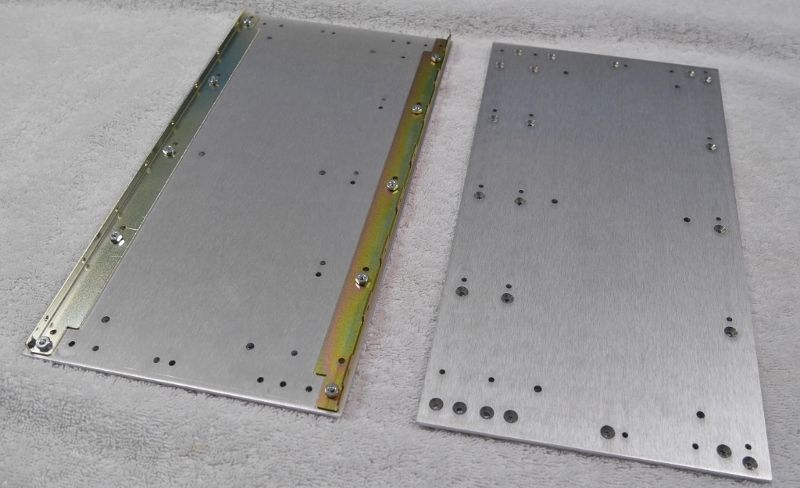
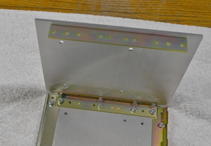
The single bucket kit consists of 2 side panels and 2 top/bottom panels.  All are 1/8" aluminum.  The machining is fantastic - all necessary holes are countersunk, everything lines up perfectly.  A friend who is a machinist looked over the panels and said a bunch of stuff I didn't understand, but it basically translated to these being very well machined.  Also, all sides had a great looking brushed finish, although some of my fingerprints might show in photos below.

The side panels:


And Top/Bottom Panels:


Shows one with rails, one without, so you can see the machining by itself.

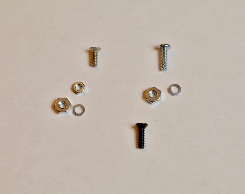
The hardware kit is pretty easy to figure out.  The black screws are for the module faceplates, angled screws for the countersunk holes, the other screws for the backplane.  The small nuts are used to connect the corner braces to the side panels.  The other nuts won't fit. 


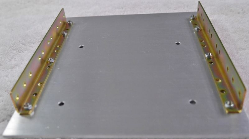
Which brings up a great feature of this kit: idiot proof.  The front and rear rails will only attach to the top/bottom panels one way, eliminating my ability to be stupid.  The only possible error I've come across (which I made) is how to attach the corner brackets to the side panels: short ends of the brackets to the side panels with the smaller nuts, as pictured:


The whole thing goes together as easy as legos.  All holes were perfectly aligned, the rails were well machined, nothing even the slightest bit warped, no having to bend something a little to get it to fit... went together perfectly.

The side panel connected to the a bottom/top:


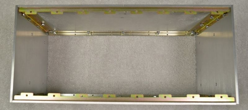
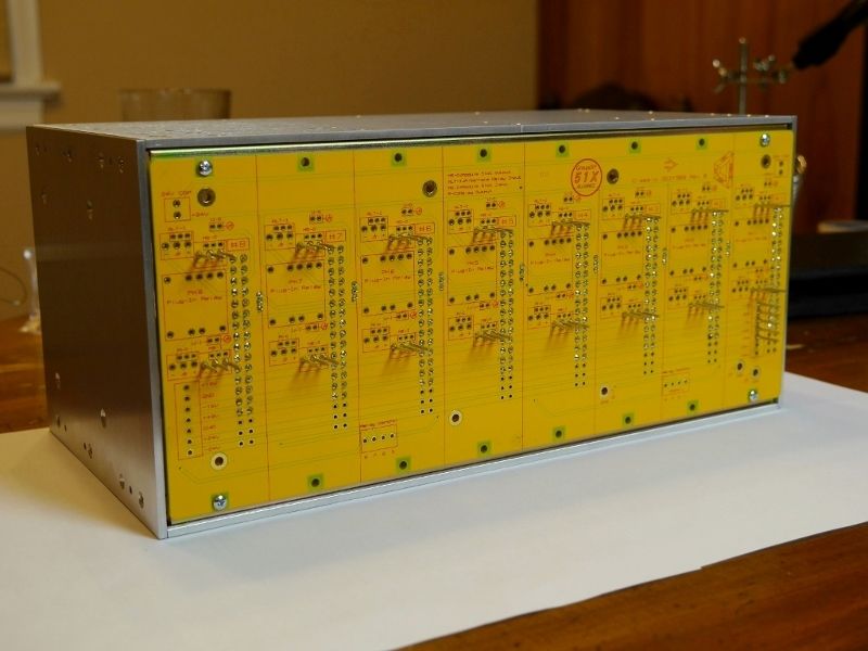
And the finished product, from the backplane side:


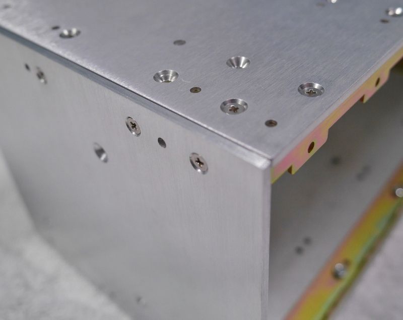
Everything fits together perfectly, and the metalwork looks great.  I tried to get a glamour shot of the corner to show the machining and overall great fit:


Next up will be the backplane build.

Thanks,

Keith

 
Step 2: CAPI/GDIY 508 backplane

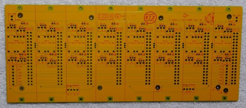
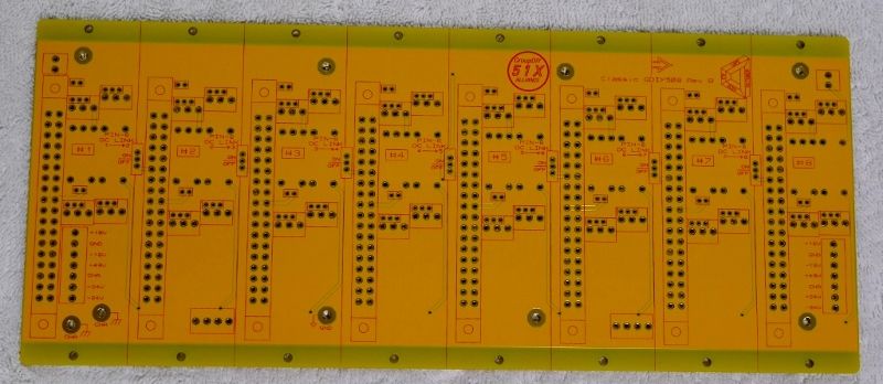
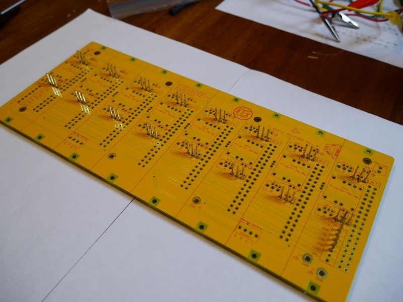
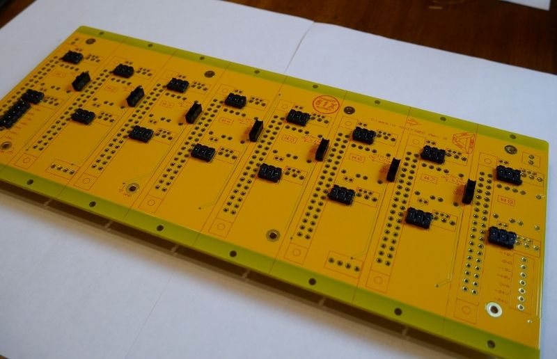
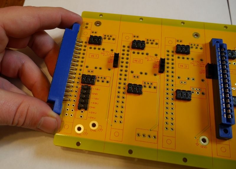
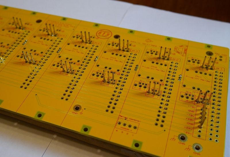
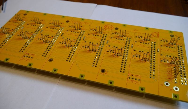
The 508 is a big chunk of pcb.  Connector side:


Module side:


There were three things to populate on the backplane: I/O headers, link switches, and card edge connectors.  Going from shortest to tallest (I soldered everything on the connector side of the PCB) I populated in that same order.

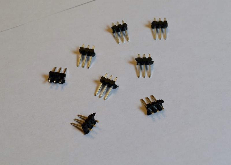
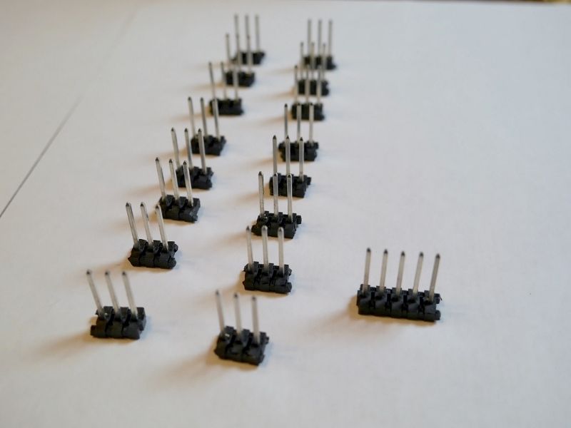
The .156 header I/O kit I got had 2 x 24 pin and 1 x 5 pin headers.  The 2 x 24 need to be cut down to 3 pin sections for the module I/O headers:


1 x 24 cut up:


I recommend trimming the extra plastic back from where you split the headers.  If not, it will interfere with the card edge connector placement later on and trying to cut that crap off after the header is soldered in place sucks.

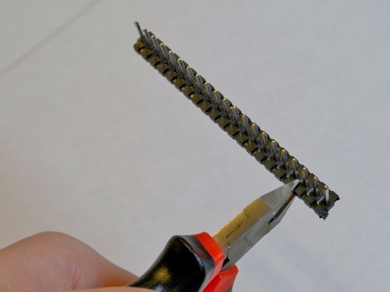
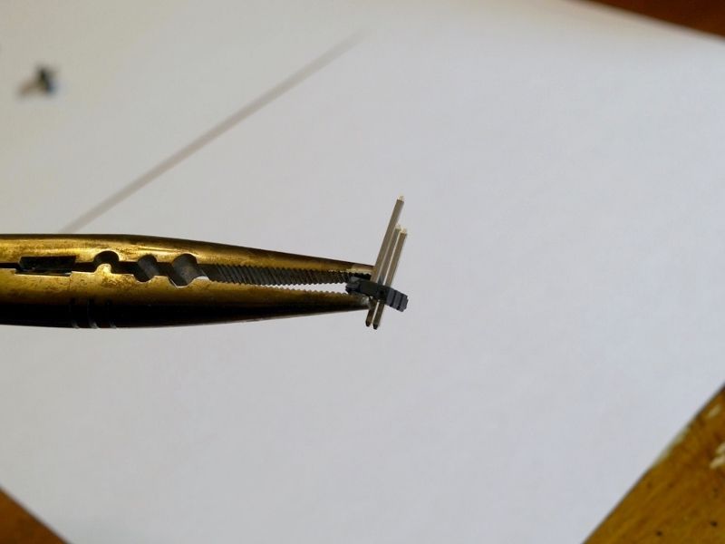
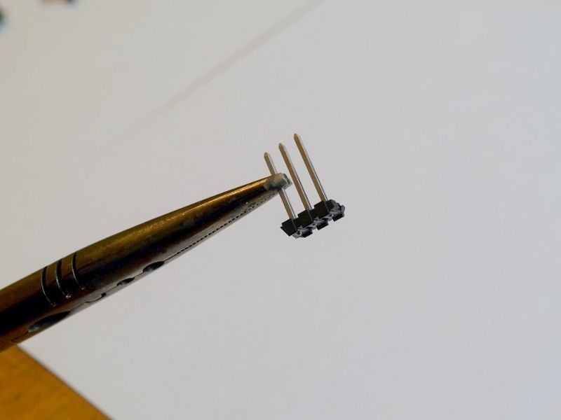
Having never dealt with headers before, I really wasn't sure what to do.  I then came across what Jeff recommends in the 2ACA documentation, to push the pins thru until they are flush with the backing.  So, I used needle nose pliers and placed the bottom of each pin in the outermost jaw of the pliers:


Some were uncooperative, but eventually they go through:


A finished header:


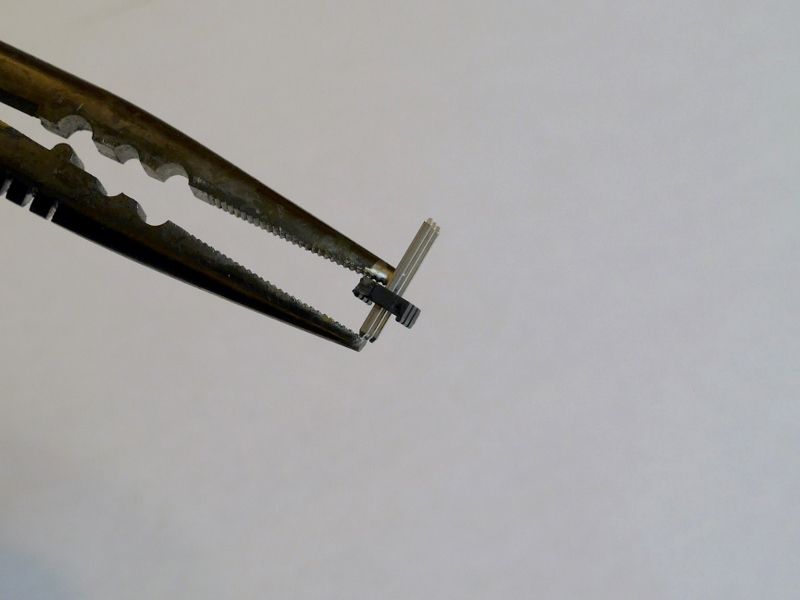
And fun with focal length and depth of field on the camera:


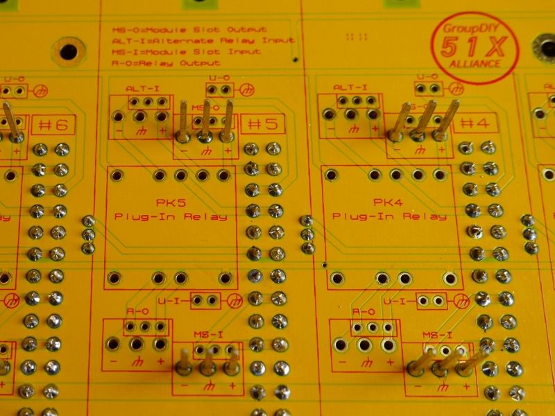
The 508 backplane has a few options for I/O connections, but for a basic 500 series rack, I only populated the MS-I (module slot input) and MS-O (module slot output) headers for each channel.  The backplane also offers footprints for relay switchable output (R-O) between MS-O and a separate input (ALT-I), which I plan to take advantage of when I eventually get to the routing portion of the project.


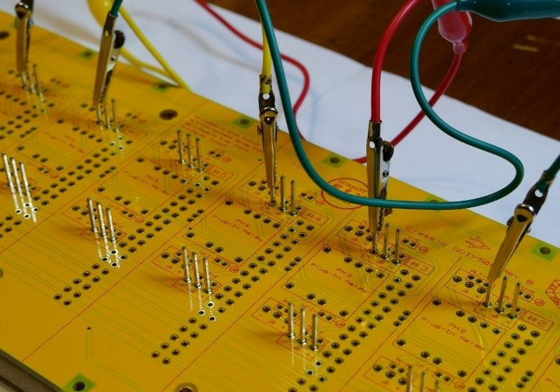
I also followed the advice from the 2ACA docs and attached alligator clips to the header pins when I soldered, to prevent solder from running up the pin.  I soldered from the connector side of the backplane:


And headers are in:


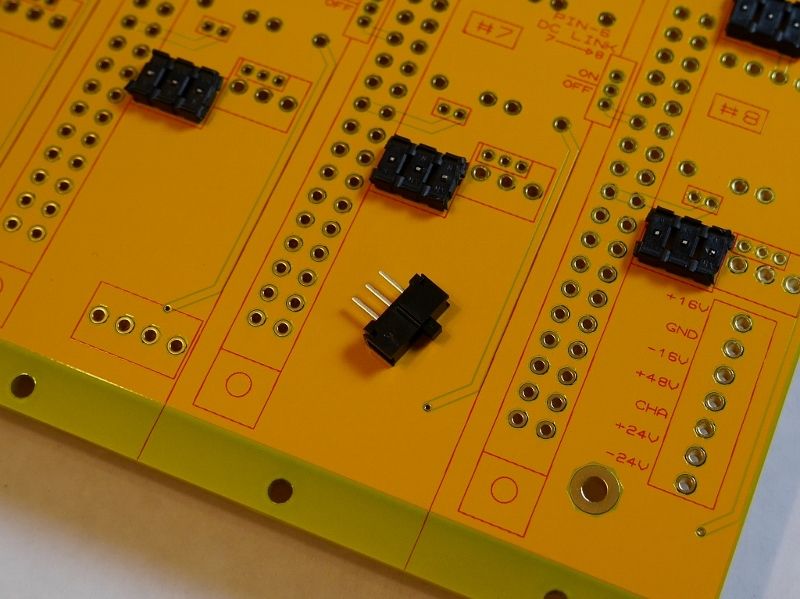
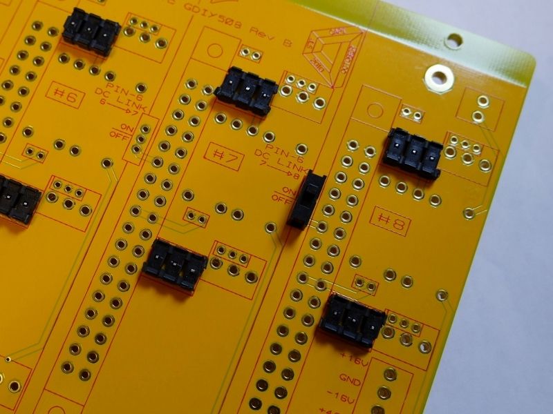
Next up in height order were the pin 6 link switches:


Placement is clearly marked.


So headers and switches are populated:


Next up is the card edge connectors.  I'm building a VPR rack, but the backplane is compatible for both VPR and 51x.  For VPR, the bottom three rows of each edge connector slot are not used:


I used a piece of cardboard to hold all the edge connectors in place while I flipped the PCB over. 


I recommend only soldering 2 pins per connector at first, then double check alignment before proceeding.  Each one of these  edge connectors has at minimum 30 solder points, and it really sucks if you don't check alignment before you solder everything (please, learn from my pain).

240 solder joints (plus some redo's) later:


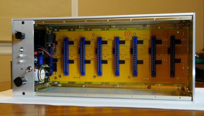
And it's ready for test fit with the rack.  Much like the rack, the backplane fit into place perfectly:


And double checking fit with a raw faceplate vp26:


We're good to go!

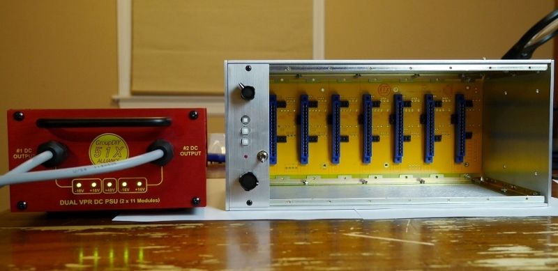
So here's where my future console stands as of right now:


Next step will be figuring out an I/O scheme.  I will post more on that later.

Thanks,

Keith

 
My initial goal is a total of 4 508 buckets in a 2x2 configuration.  Classic API sells double height side panels that I have already bought.  I just need my cash flow to catch up post-holidays so I can get 4 more top/bottom panels to complete the 2x2 buckets.

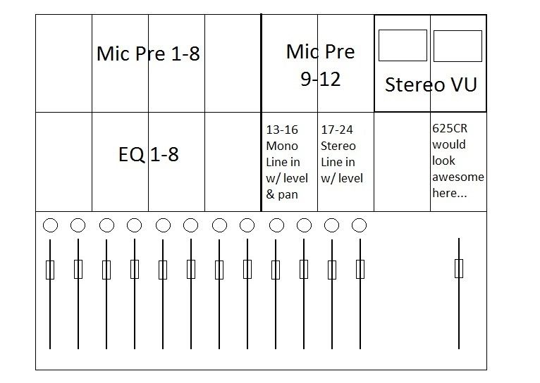
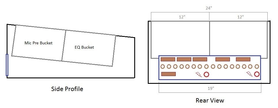
Here's what I am envisioning for the "Mark I" of this project (please enjoy my Microsoft Paint skills).  Each rectangle represents 2 x 508 slots, in case it isn't obvious:


Console might be a bit strong of a word, as it will really be a DAW front end with 12 mic pres/8 eqs, and then a 24 channel summing mixer with a single stereo bus.  For this I plan to use the Stereotype Mark 5 PCB's I bought off Hakanai a while back.  These offer a pretty simple summing mixer with DOA inputs and fader/pan for each channel, summing to a single stereo bus.  This will then go to a Classic API 2ACA.

However, that's all much further down the road as first I need to figure out an I/O connection scheme.

I think the easiest route will be getting a custom punched 19" 3U rack panel from Redco.  Here's what I'm thinking for an initial frame and how this would look.  Note that absolutely nothing is to scale: 


A good friend of mine does cnc wood carving for a living, so he will be making the side and rear panels for the frame. 

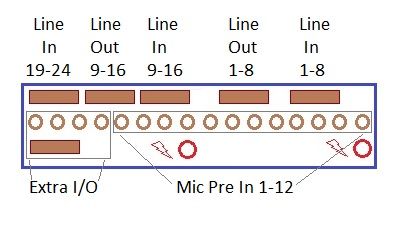
Here's the I/O panel layout labeled:


Mic pre inputs on xlr's 1-12, 13-16 as extra... I'm sure there's plenty of I/O I haven't considered yet, so I also think an extra db25 connector would be prudent.  Line in 1-24 and Line out 1-16 are all db25 as well.  The power connectors are 5 pin xlr to mate with my GDIY floorbox PSU.

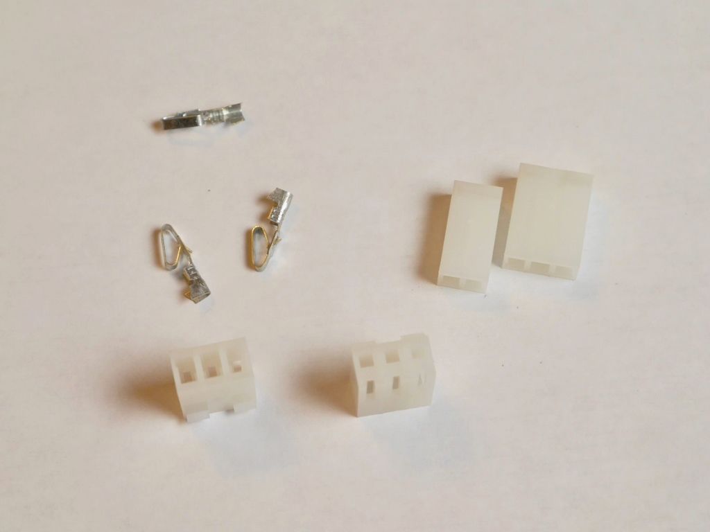
I still need to read through the Rane notes on grounding that Jeff links to from his site a few more times to get a better understanding of how I should wire everything.  I also need to do some crimping practice as I will have a bunch of these to put together:


My initial focus will be wiring up xlr in 1-12 for the mic pres and line out 1-16 on db25 to run to the DAW.  I've soldered together plenty of xlr cables in my day, but that's pretty well idiot proof.  I feel totally lost on this though, so I have some very basic questions:

1) What kind of wire would I use between the xlr connector on the backpanel and the header on the backplane?  Just regular hookup wire?  Do I need to use something shielded?  I'm thinking total distance between backpanel connector and 508 backplane header is 12-15 inches of wire.

2) Chassis ground - what acts as the chassis in this situation: the 3U metal backpanel, the 508 rack, or both?  Would I need to ground one to the other?

Like I said, I still have some more reading to do... question 1 however is something I've been trying to figure out for a while, and just can't seem to find anything definitive.

That's all I have for now.  Thanks in advance for any help provided.

Thanks,

Keith 
 
Krcwell

Glad you reposted this thread after the loss in the software upgrade.

I am a big fan of Jeff's 508  "console erector set goodies" I use a lot of
these parts on my Sphere sidecar build.

http://groupdiy.com/index.php?topic=45733.msg606424#msg606424

http://groupdiy.com/index.php?topic=45733.msg681578#msg681578

Use Mogami W2944 console cable for all your signal wiring.  This stuff
is very easy to work with and is much smaller that Belden 8451.
Redco seems to be about the cheapest and carries 10 colours.

http://groupdiy.com/index.php?topic=45733.msg698468#msg698468

Have fun... nice project

BTW .. nice "chungerest"  pics! :)

GARY
 
Thanks Gary. I was kinda disappointed that the first posts got lost, but I also think I did a better job on this second round... Also saved them to a text doc just in case.  ;)

Looks like I will be adding some W2944 to my redco order. Appreciate the advice!

I need to go back through your build thread again. I haven't done so since I started conceptualizing this project. Although that last link you posted damn near made me go cross-eyed. That's some insane wiring! Very good inspiration to keep good cable management at the forefront of planning.
 
I built 2 X 508 kits myself which I am running off a small soundcraft PSU. yeah it's overkill for the needs but it was a scratch and dent special.  they are working perfectly.
 
It's been an extremely cold and nasty week in the greater Chicagoland area, which has not only doubled or tripled my normal work commute, but also delayed receipt of much anticipated deliveries.  UPS was supposed to deliver my i/o backpanel and a whole bunch of W2944, but weather caused delays, so I will get that tomorrow.  The US Postal Service was supposed to deliver my order from CAPI on Thursday, but also, weather delays. Fortunately, the USPS still delivers on Saturday, and a fresh batch of metalwork showed up on my doorstep yesterday afternoon.

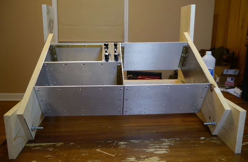
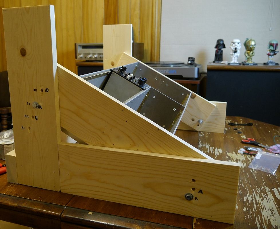
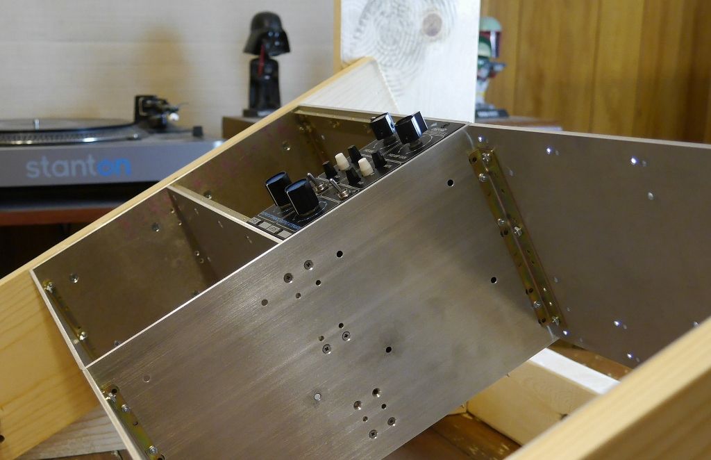
Since it's too damn cold outside to do anything, I decided to slap some scrap lumber together into a test frame.


I had some random 1x6, so screwed the rack to a couple of pieces, then made an L frame.  I'm just using a thick bolt at top and bottom so I can adjust the angle, see what feels good before moving on to a more permanent frame.  I drilled A and B holes in the bottom of the L and numbered holes in the top.  This allows for a few different angles and heights.  The fact that the top holes lined up for both the A and B bottom holes was a very happy coincidence.


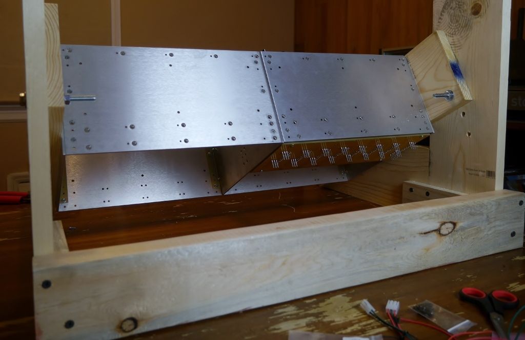
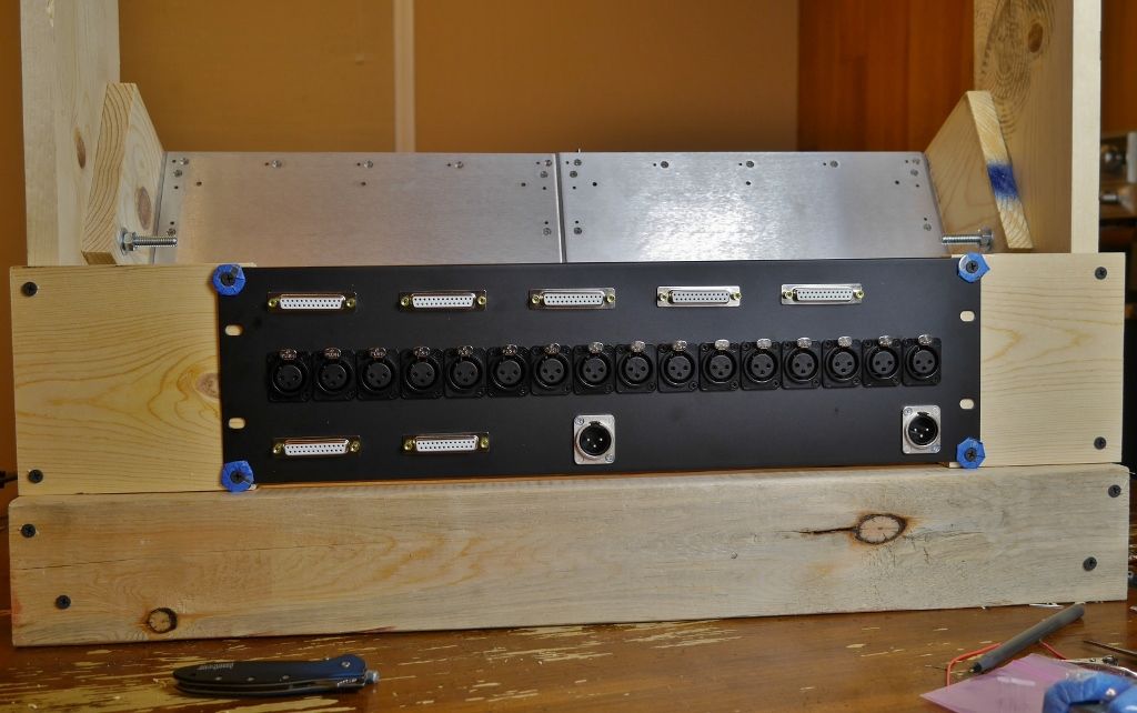
Here's the back.  I'll slap together some sort of support to hold the i/o backpanel when it comes so I can start test wiring.


Always watching over, ensuring progress.


Questions to come when I start in on the wiring. 

Thanks,

Keith
 
gar381 said:
I will be watching your build with much interest.....

Well played, sir.

Another batch of snow for the evening commute, so another 2 hours in the car, including my stop by UPS to pick up my shipment from Redco: a custom 19" panel and some Mogami w2944, 50ft each of 3 colors.

A quick run with the chop saw and a drill:


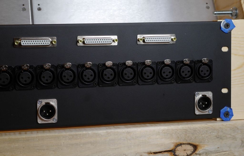
Now, the astute observer will notice that, instead of the 5-pin xlr for the power, Redco accidentally installed 3-pin. 


It says 5 pin on the packing list, the work order, everything... I sent them an e-mail as it was after office hours, so I will catch up with them tomorrow to get the 5 pin connectors I ordered sent out.  Bonus: a couple free male xlr connectors.  Downside: I really want to hook the damn power up!  My floorbox PSU has been just sitting there, doing nothing...

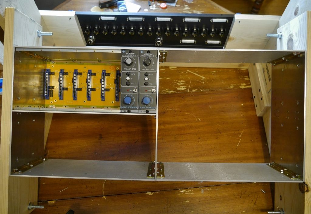
So here's where I'm at:


I have a little 5 fish PSU I built as my first project, so I think tomorrow I will try to wire it up to the 508 backplane so I can start testing some i/o wiring with the vp26's.  Hopefully I get the correct 5 pins from Redco by the end of the week.  Wiring this up seems like a good weekend project. 

Keith
 
what fader are you going to use? I have been considering TKD faders but have not continued work on my mixer project so far. considering a group buy?

http://www.tkd-corp.com/products/fader/pdf/cpa7000s-e.pdf , 104mm travel, 5k or 10k audio

What dou you think?

- Michael
 
audiomixer said:
what fader are you going to use? I have been considering TKD faders but have not continued work on my mixer project so far. considering a group buy?

http://www.tkd-corp.com/products/fader/pdf/cpa7000s-e.pdf , 104mm travel, 5k or 10k audio

What dou you think?

- Michael

I need to order some random pots from AML, so I'm going to also get a few of the alps 10k mono faders that they carry to start playing around with.  I would love to use the P&G 1k mono faders that Classic API carries, but unfortunately I can't afford those in the near term.  I will be getting one of the P&G stereo 1k faders for the master though.

Hopefully someone can enlighten me... The Hakanai stereotype mark 5 boards I plan to use for the summing bus call for 1k pots/faders for level, which seems to be the API style norm. By using a 10k fader instead, it is my understanding that I will probably want to use some sort of buffer circuit after the fader, I believe this would be a voltage follower? I've referenced some schematics Hakanai has floated around for his as-yet-to-be-released channel boards, and he's using a 2520 after a 10k fader before heading to the pan pot and post fade sends, etc...

http://hakanairecording.com/mixerpics/markVpics/Stereotype-5.pdf

(Can someone let me know if it's poor ettiquette to link to Hakanai's schem?)

So the 10k fader vs. 1k fader, what's going to be the main differences? What is the buffer doing? Impedence, unity gain, etc...?  I had planned on some sort of buffer after the 10k's, whether thats a gar2520 (i'm going to need to set up an assembly line for these soon, I'll be using A LOT of them) or something like Classic API's little 3 transistor voltage follower:

http://classicapi.com/catalog/product_info.php?cPath=71_72&products_id=221

Once again, any help is greatly appreciated.

Thanks,

Keith
 
Keith

Colin's K series Alps faders at AML are a great bang for the buck fader.

http://www.audiomaintenance.com/acatalog/faders_carbon.html

They do have a nice sort of P&G ish feel to them. 
My gar2520s do make a dandy fader amp.

Nice Redco panel BTW.  Those boys do nice work..

Carry on......

GARY
 
gar381 said:
Nice Redco panel BTW.  Those boys do nice work..

Carry on......

GARY

I wanted to mention that, thanks for reminding me.

I had an issue with two wrong connectors installed on the panel, I sent Redco a message through their website last night, and had a reply from Chris at Redco waiting for me when I got to work this morning. About an hour later, just after grabbing a cup of coffee, I had a tracking number for the replacement connectors. Damn good personal service, I can understand the mistake from the assembly department... 16 female xlr's then all of the sudden two random male 5 pins? It's an easy mistake to make when I'm sure 90% of the panels they assemble only involve 3 pin xlr's.

A custom, fully populated panel, extremely well done, and woulda been on my doorstep 4 business days after I ordered it if it weren't for some damn polar vortex (thanks, Canada), for $70. All connectors included in price and installed. Had I ordered the connectors alone it would've been close to $60.

They have a great online tool for designing your own panel with whatever the hell connectors you want. When I think about it, it's pretty ridiculous how little this panel cost me.

In short, +1 Redco.
 
Replacement 5 pin male xlr's arrived from Redco the other day, and now that I've found a little free time, I should start wiring some stuff up.

I wired up some of the .156 header receptacles with some 22awg stranded wire a few days ago to get some practice crimping the contacts for the receptacles.  After ruining a few with only one usable crimp to show for it, I decided to hell with crimping (I don't have the proper tools) and would just solder the contacts to the wire.  I did still crimp the insulation tabs to the best of my ability.

Anyways, soldered that to the 5 pin male xlr, then once again triple checked the +/- 16v and 48v against ground with my dmm to ensure I had wired everything properly.  Couldn't get a picture of that since I lack a third hand.


I left the other 3 pin male xlr in the backpanel as I will use that for initial test wiring; much easier to use an xlr for a line out than to jack around with db25 at this early stage.

PSU hooked in to the backplane:


I double checked voltages at the card edge connector, and so far, success!  At least the phantom leds light up!


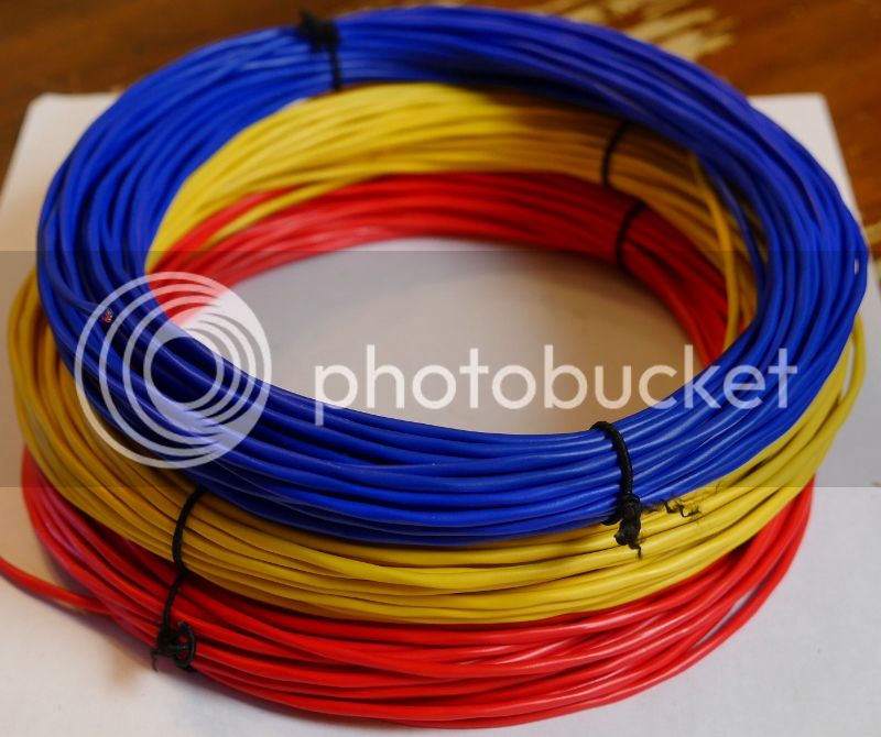
Now, time to wire up some i/o connections.  Per Gary's advice, I picked up some Mogami w2944.  Really easy to work with, and the colors are bright and vibrant:


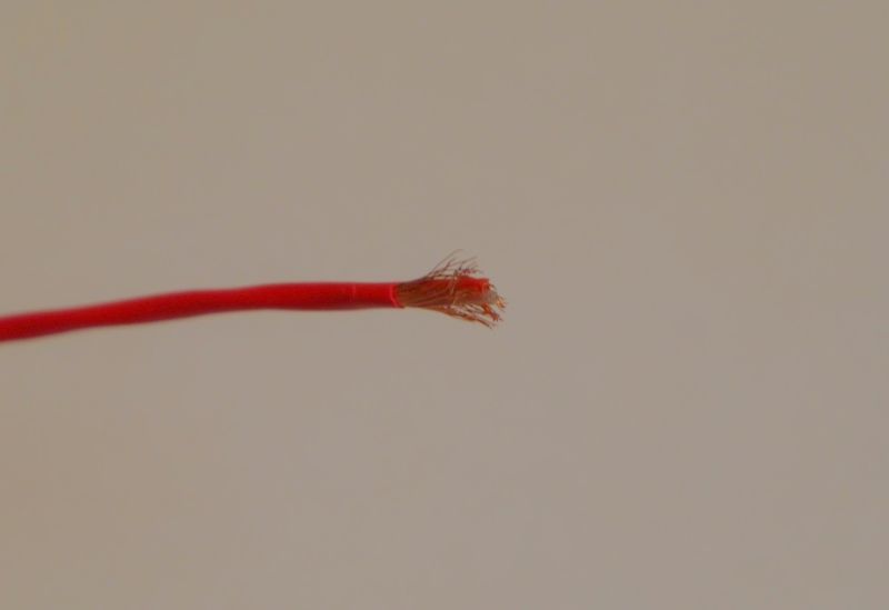
Time to dig in and see what we got here.  I stripped back the outer layer of insulation:


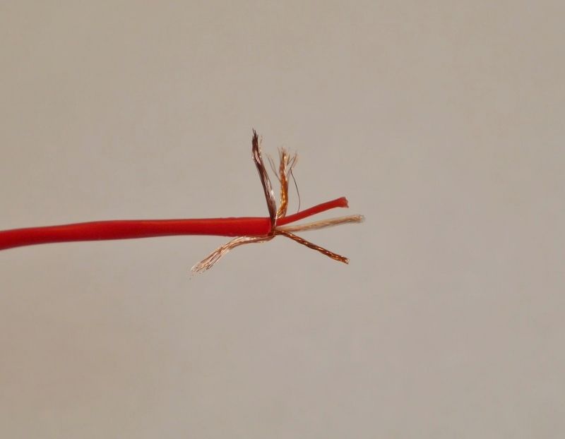
Pulling back the random bits of shield reveals a red, a white/clear, and nicely twisted drain wire.


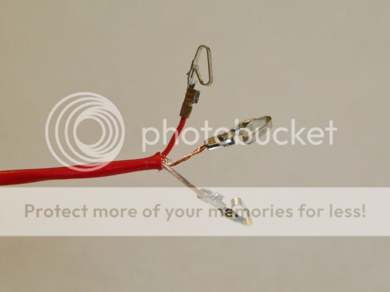
And the shielding cleaned up:


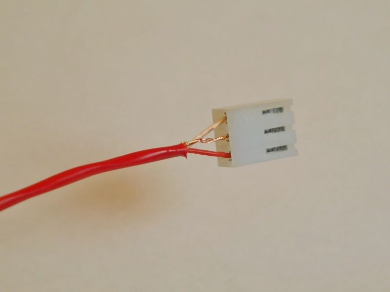
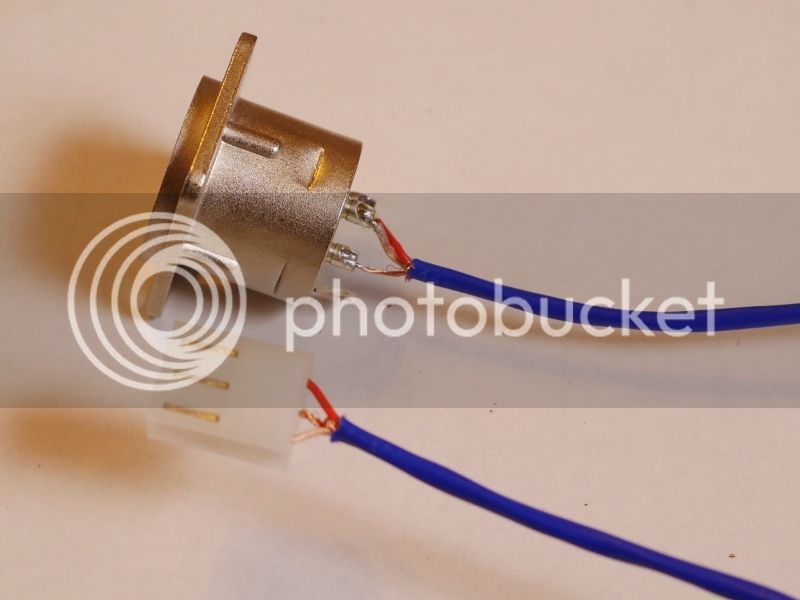
The individual wires are 26awg, so I didn't see any chance of trying to crimp into the insulation.  I'm sticking with soldering, bending a little here and there to ensure fit into receptacles.


And one mic in backplane connection completed.


For the line out (module slot output) I used some of the blue w2944.  For the time being I have the shield connected on both ends.  I'll post my current understandings and questions on grounding in the next post, as it will be much more rambly and will get lost in this one.


Mic in and line out xlr's reinstalled in backpanel:


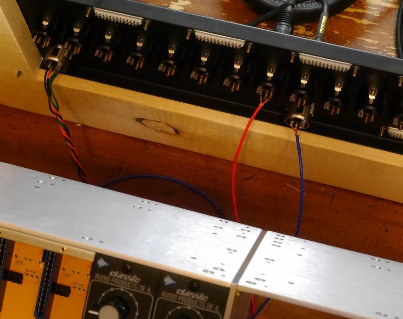
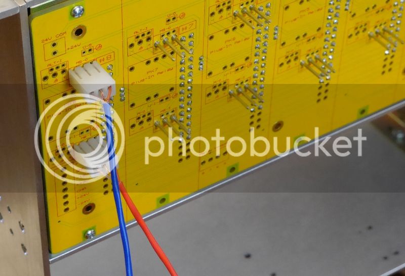
Appropriate connections on 508 backplane: red (mic in) to MS-I (Module Slot Input) and blue (line out) to MS-O (Module Slot Output):


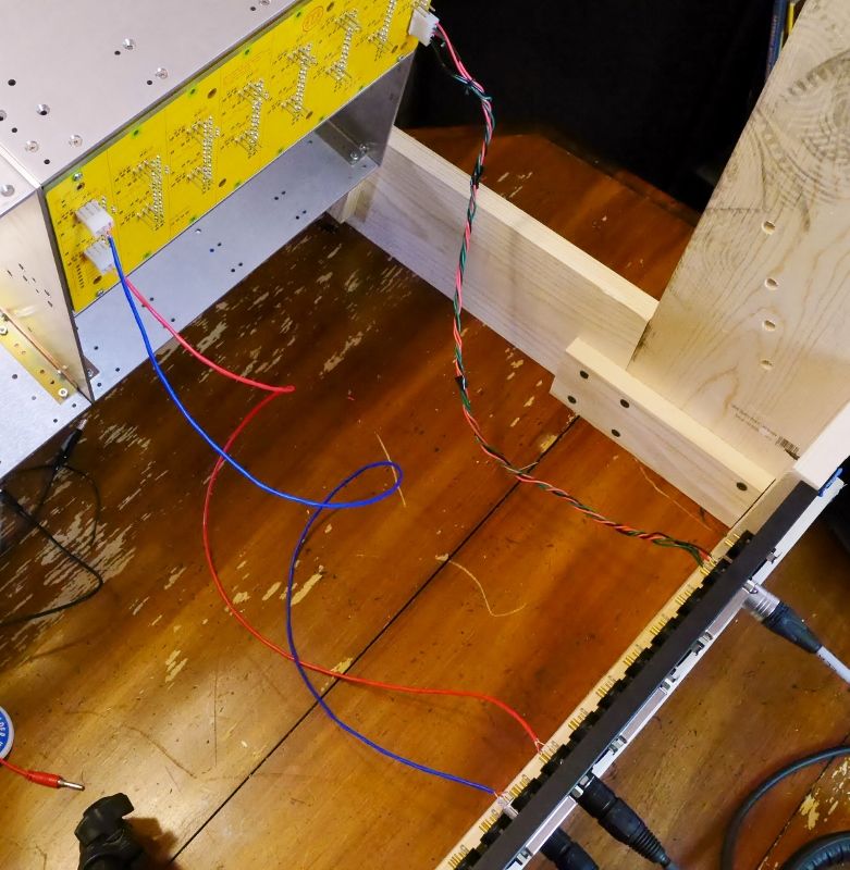
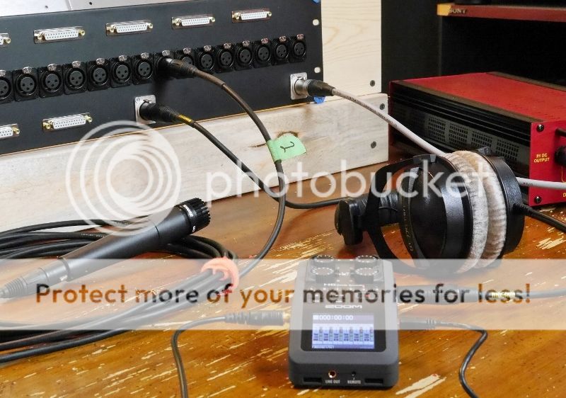
And from cradle to grave, so to speak.  Using bolts on the test frame really makes it easy to get to the wiring.


To test everything out I used a little zoom h6 I picked up a while back.  It's a lot easier for testing than dragging the console  downstairs to the studio or dragging the pro tools rig upstairs.


And success!  I tested with both dynamics and condensers, and no noticeable noise, hum, etc... anywhere. 

I'm confident in the xlr in connections, so I will get to work wiring the rest of those up.  For the line out, I have some questions after going through info on Jeff's site and the RANE notes on grounding.  I'll put those in another post a little bit later.

Thanks,

Keith
 
Back
Top