Still learning design preamp with LTspice(Some help please)

GroupDIY Audio Forum

Help Support GroupDIY Audio Forum:

This site may earn a commission from merchant affiliate links, including eBay, Amazon, and others.

ForthMonkey

Well-known member
Joined
Sep 4, 2013
Messages
1,115
Location
Turkey
I'm still learning design with LTspice.I have idea.Transformer input and one op amp mic preamp.But op amp is discrete.It's like API Style.So i started with simple discrete op amp.

uroa~0.jpg


It's working good.But i won't make like 2520 op amp.I wwant to build only one circuit like discrete mic preamps...

Then i looked Forsell API Preamp.And i simulated it with LTspice.

It's circuit.Circuit uses 10K pot for gain.So i use 10K to measure full gain.


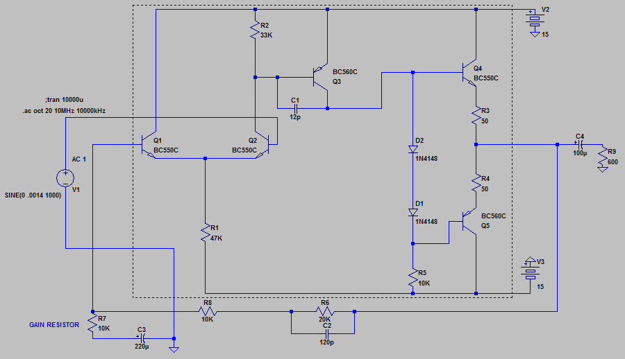
It's transient.Gain resistor:10K.


It's AC analysis.10mHz-10MHz.
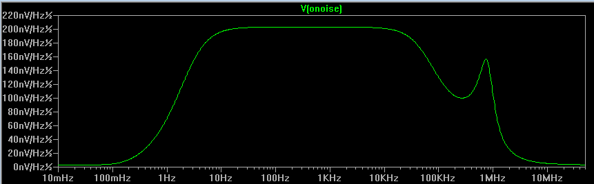


Noise 10mHz-60MHz


What do you think?

 
Are there any DC voltages in there?

Your AC voltages "suggest" the DC conditions are good. But NEVER bet that SPICE is as smart as a pocketful of transistors. Always look for rational DC voltages throughout a circuit.

Also, since you are not limited by practical test gear, run the AC sweep from sub-Hz to many MHz. Many jellybean circuits are prone to 10MHz peaking even in simulation. On breadboard a good peak can become outright oscillation. OTOH, some circuits (probably not this one) can be peaky sub-sonic; one widely sold phono preamp had a good (bad) bump near 0.55Hz (warp-rate of a 33rpm LP).
 
Input voltage should be mic level (I use .0014v). Don't forget DC blocking caps either.

PRR made a good point about checking extended frequencies! (Something I never did but will now!).

That is a nasty bump. I though that the feedback cap would roll off the high end?
 
Indecline said:
Input voltage should be mic level (I use .0014v). Don't forget DC blocking caps either.

PRR made a good point about checking extended frequencies! (Something I never did but will now!).

That is a nasty bump. I though that the feedback cap would roll off the high end?

Thanks for reply.I will use voltage as mic level and add DC blocking caps.

BTW i will use 1:10 input transformer.It's ok for API style mic pres.
 
ForthMonkey said:
How i can test it?I'm reading 75.06mV at out.
With the resistor values you have set, the gain is 12dB or x4, so running the input at 1.4mV should give 5.6 mV at the output, which looks correct.
Beware that these are peak voltage, not rms.
In yout schemo, the NFB resistor is 30k (R6+R8). Capacitor C2 sould be across both (going from the output to the negative input; you should see a difference in the response graph at 8MHz.

In practice, if you do actual measurements with 1mVrms at the input, it is very likely that the output signal will be seriously noisy, up to a point you may not assess correctly the amplitudes. You should use an input voltage that gives a hefty output signal.
You should set the input voltage V1 according to the gain.
Your circuit is powered with +/-15V rails so you should expect a max output voltage of about 10Vrms.
With 12dB gain, you may increase the signal to about 2.5Vrms and get 10Vrms at the output. If the opamp operates correctly the signal should not be visibly distorted.
Now if you set the gain at 45dB or x180, you should decrease the input voltage to about 55mVrmsfor the same 10V output.
 
> Input voltage should be mic level

Mikes and sources vary ALL over the place.

OUTPUT voltage should be LINE level. Call it 1V, more or less. Not critical, but well above hiss and well below overload.

Cuz Line Level is what we are going to want. That's how we will twist any GAIN control we find. So that "normal" settings on mixer/recorder give "nominal" readings on meters.

As Abbey says, once you find reasonable performance around 1V output, you do want to slam it hard and see how it handles distress. For most studio stuff this is around 10V (RMS; in SPICE you probably look for 15V peak output.)

The .AC card (your "AC sweep") is NOT level sensitive. SPICE uses a hypothetical small-signal analysis. For example your .AC source may be set to 1V, amp gain of 100, notional output 100V, under 15V rails. In real life it clips. But SPICE .AC uses a "1V" source only as a scaling factor. The internal math assumes infinitesimal signal level.

You do need to find the waveform display, classically .TRAN with a .PROBE chaser. Modern SPICE packages may be neater. If you can drive the output past 15V and see the clipping, that's fairly realistic.

> i will use 1:10 input transformer.

Input stage current is fairly high, ~~0.14mA per device. (Confirm this on your simulator.)

At that current the OSI is likely to be several K Ohms. Not ~~20K like a typical mike through a 1:10 transformer. Lowest hiss will be with 1:3 or 1:4 transformers. May not be a huge difference, and I have seen such amps with high-ratio iron. But if you are studying design, something to learn.

> a nasty bump. I though that the feedback cap would roll off the high end?

It starts to. But it also adds a phase-shift. You already have shifts in stage 1 stage 2 and stage 3. It only takes two good shifts to bump, three to oscillate.

I'm not 101% sure that re-rigging C2 will tame this bump. But worth a try.

As a stone-age designer I'd make C1 much larger. It merges the 1st and 2nd stage phase-shifts into a single pole. However you also lose gain-bandwidth. And Slew.

One subtle thing to ask: what is the idle current in q4 Q5? SPICE will use that to set up the .AC analysis. We don't actually know (from basic calculation) what Q4 Q5 current is. It depends on "matching" of diodes against transistors. SPICE's models may have told it that Q4 Q5 run at very low current. Which will make them very slow. In real life we would not want very low Q4 Q5 current (we want ~~>50mV across the emitter resistors); also under any non-infinitesimal signal Q4 Q5 current will rise enough to make them fast, so that 6MHz bump may vanish with any signal big enough to read in a real world.
 
I'm trying to understand what you wrote...

One subtle thing to ask: what is the idle current in q4 Q5? SPICE will use that to set up the .AC analysis. We don't actually know (from basic calculation) what Q4 Q5 current is. It depends on "matching" of diodes against transistors. SPICE's models may have told it that Q4 Q5 run at very low current. Which will make them very slow. In real life we would not want very low Q4 Q5 current (we want ~~>50mV across the emitter resistors); also under any non-infinitesimal signal Q4 Q5 current will rise enough to make them fast, so that 6MHz bump may vanish with any signal big enough to read in a real world.

Q4:77.4mV
Q5:72.7mV

As a stone-age designer I'd make C1 much larger. It merges the 1st and 2nd stage phase-shifts into a single pole. However you also lose gain-bandwidth. And Slew.

If i use larger vales,i losing high freqs.But with 12pF it's good and there is no bump.

BTW i want more bass response.If use larger values for C4,i getting more bass.

And really thanks for explanation.But can you talk like you're talking with idiot?Cause my English is not good and i have no knowledge about design.Still learnin&understanding...
 
ForthMonkey said:
BTW i want more bass response.If use larger values for C4,i getting more bass.
The impedance of a capacitor obeys the formula Zc= 1/2.pi.f.C, which can be rewrit as C=1/2.pi.f.Z
Good design rule is to calculate Z at lowest frequency of interest about 1/10 of the load.
For 600r load and 20Hz lowest frequency, the capacitor's impedance should be less than 60r.
Hence C=1/2.pi.20.60 => 133uF which will give a -3dB turnover frequency of 2Hz and -0.6dB at 20Hz
But you must also calculate the value of C3 for the highest gain (lower value of R7)
With R7=100r, C3 must be >80uF
You have used 250uF, which is adequate for R7=33r (about 60db gain), so it appears that the truncated LF response is due only to the low value of C4.
 
> If use larger values for C4,i getting more bass.

I didn't see that. Whoa, 10uFd is tiny for 600 Ohms!

You MUST get an "instinctive feel" for how big a cap must be to pass low audio.

My guide-posts are:

10uFd can drive 1K to 17Hz

0.01uFd can drive 1Meg to 17Hz

Other impedances take other caps. 8 Ohm (speaker) is nearly 10 Ohms, which is 100X lower than 1K, so needs 100X bigger cap, or 1,000uFd.

17Hz sounds low, but often isn't.

One 17Hz roll-off from mike to speaker is OK. When you have dozens of stages in the chain you will aim each one much lower.

While 10uFd into 600 Ohms is 30hz, and will pass music well, it is really Too Small.

Plagiarize!! What do other 600r drivers use for an output cap? 50uFd is cheap. I have seen 500uFd.

A non-SPICE issue: caps this size will be Electrolytic. Which distorts. But distorts less when the audio voltage-drop across the cap is smaller. Which means over-size this cap. Which may be the real reason 250uFd-500uFd is often used.
 
I calculated gain resistors for 12 positions switch.

Now if i use 1:10 transformer,i will get 20dB.Then i will add minimum circuit gain.It's 15dB.35dB gain minimum gain,right?I calculated resistors 35dB to 60dB.2dB steps.Last step 3dB.

I've used this link;

http://www.sengpielaudio.com/calculator-gainloss.htm

And what i calculated;

Ohm  - dB
6400 - 35
4900 - 37
3750 - 39
2900 - 41
2250 - 43
1760 - 45
1370 - 47
1080 - 49
850  - 51
670  - 53
525  - 55
410  - 57
285  - 60

2dB steps is goof for fine tuning,i guess.
 
ForthMonkey said:
I calculated gain resistors for 12 positions switch.

Now if i use 1:10 transformer,i will get 20dB.Then i will add minimum circuit gain.It's 15dB.
Who says? Depending on compensation, this circuit should be good for unity gain (0dB).
I calculated resistors 35dB to 60dB.2dB steps.Last step 3dB.
there's no point making the steps so small. Any signal worth recording has much more variance so you would be constantly fiddling with the gain knob trying to find an optimum.
As PRR suggested, you should plagiarize. Most commercial implementations use 5 - 10 dB increments with an additional continuous gain control (potentiometer).
 
??? OK.I'm all wrong.So i'm turning to start point.

Now with this circuit i'm getting minimum 12dB with 10kohm and getting 40dB when gain resistor is 285 ohm with -3dB loss at 60kHz.And with 40dB freq. response is almost flat between 5Hz and 25kHz(+/-0.5dB).25kHz to 60kHz,there is 3dB loss.I think freq response is good.

But if i use potantiometer for gain,my maximum gain will be 65dB with serious freq. loss.I want to 285 ohm for maximum gain.How can i figure it out? With potantiometer i'll get really small value.I don't want it.Or do i think wrong?

1:10 ratio not 20dB? 20dB+40dB okay for mic preamp,i guess.Wrong?

With this and 1:10 transformer,how much dB can i get?
 
ForthMonkey said:
Now with this circuit i'm getting minimum 12dB with 10kohm and getting 40dB when gain resistor is 285 ohm with -3dB loss at 60kHz.And with 40dB freq. response is almost flat between 5Hz and 25kHz(+/-0.5dB).25kHz to 60kHz,there is 3dB loss.I think freq response is good.

But if i use potantiometer for gain,my maximum gain will be 65dB with serious freq. loss.I want to 285 ohm for maximum gain.
Then you put a 285 ohms resistor in series with the potentiometer. The problem with potentiometers in this application is that you need a reverse log taper. Let's say you want 40dB range. With a pot you cannot get down to 0dB gain, so you have to compromise, let's say you make the gain pot equal to the NFB resistor (s), that will make 6dB minimum gain (26dB with the xfmr), so your max gain will be 46dB (66 with the xfmr). The padding resistor (the resistor that you have to connect in series with the pot for regulation of maximum gain) willl be 200 times smaller. In order to get a nice progression of gain (26dB at mid-position), the value of the potentiometer at mid position would be about 1/20th of the pot value. That defines a 5% Reverse-log taper, which is rare. Most revlog pots are 10-20% taper.
OTOH, a rotary switch can emulate almost any taper, and in particular a position of infinite resistance that allows 0dB minimum gain.
 
abbey road d enfer said:
ForthMonkey said:
Now with this circuit i'm getting minimum 12dB with 10kohm and getting 40dB when gain resistor is 285 ohm with -3dB loss at 60kHz.And with 40dB freq. response is almost flat between 5Hz and 25kHz(+/-0.5dB).25kHz to 60kHz,there is 3dB loss.I think freq response is good.

But if i use potantiometer for gain,my maximum gain will be 65dB with serious freq. loss.I want to 285 ohm for maximum gain.
Then you put a 285 ohms resistor in series with the potentiometer. The problem with potentiometers in this application is that you need a reverse log taper. Let's say you want 40dB range. With a pot you cannot get down to 0dB gain, so you have to compromise, let's say you make the gain pot equal to the NFB resistor (s), that will make 6dB minimum gain (26dB with the xfmr), so your max gain will be 46dB (66 with the xfmr). The padding resistor (the resistor that you have to connect in series with the pot for regulation of maximum gain) willl be 200 times smaller. In order to get a nice progression of gain (26dB at mid-position), the value of the potentiometer at mid position would be about 1/20th of the pot value. That defines a 5% Reverse-log taper, which is rare. Most revlog pots are 10-20% taper.
OTOH, a rotary switch can emulate almost any taper, and in particular a position of infinite resistance that allows 0dB minimum gain.

Thanks for explanation.But...What if i use linear 10K potentiometer?I started this circuit with Forsell API preamp.This circuit uses 10K linear.But at half position(5K) gain is 16.5dB.I think i can't use linear...

http://www.jefflaity.com/albums/API-Forsell-Preamp/Forsell_API_preamp.sized.gif

And i tried adding 285 ohm resistor without transformer gain.When gain resistor is 1 ohm,i'm getting 40dB.And when gain resistor is 10K,i'm getting 12dB.Why my minimum gain is 6dB? I didn't understand...It should be 12dB,i guess.Because input 1.4mV.When gain resistor is 10K,output is 5.6mV.And 5.6mV is 12dB,right? And when gain resistor is 285 ohm,output is 140mV.So i'm getting 40dB...
 
ForthMonkey said:
And i tried adding 285 ohm resistor without transformer gain.When gain resistor is 1 ohm,i'm getting 40dB.And when gain resistor is 10K,i'm getting 12dB.Why my minimum gain is 6dB? I didn't understand...I should be 12dB,i guess.Because input 1.4mV.When gain resistor is 10K,output is 5.6mV.And 5.6mV is 12dB,right? And when gain resistor is 285 ohm,output is 140mV.So i'm getting 40dB...
So you have only 28dB gain range, which is not much to cope with the large range of signals that a microphone can deliver.
Dynamic microphone on acoustic guitar, about 1mV (-58dBu), condenser mic on violin 10mV, dynamic mic in kick drum 100mV, condenser mic on kick drum 1V (+2dBu). That's 60dB range. You need about 40dB range on primary gain, 20dB input pad and continuously variable gain trim +/-6-10dB.
 
abbey road d enfer said:
ForthMonkey said:
And i tried adding 285 ohm resistor without transformer gain.When gain resistor is 1 ohm,i'm getting 40dB.And when gain resistor is 10K,i'm getting 12dB.Why my minimum gain is 6dB? I didn't understand...I should be 12dB,i guess.Because input 1.4mV.When gain resistor is 10K,output is 5.6mV.And 5.6mV is 12dB,right? And when gain resistor is 285 ohm,output is 140mV.So i'm getting 40dB...
So you have only 28dB gain range, which is not much to cope with the large range of signals that a microphone can deliver.
Dynamic microphone on acoustic guitar, about 1mV (-58dBu), condenser mic on violin 10mV, dynamic mic in kick drum 100mV, condenser mic on kick drum 1V (+2dBu). That's 60dB range. You need about 40dB range on primary gain, 20dB input pad and continuously variable gain trim +/-6-10dB.

So first i need 40dB to drive any mic.Then i need variable gain control between 40dB and 60dB.And 20dB input pad to decrease if input signal too high.Am i right?

If i'm right...When gain resistor is 285 ohm,gain will be 60dB with xformer.It's maximum gain.And when gain resistor is 3.3K,minimum gain will be 40dB with xformer.And i can make 5dB-4 steps gain switch.
 

Latest posts

Back
Top