

With that many channels, the bus impedance is 700 ohms, which would justify using a VLN opamp.My console has at least 66 channels going to the master bus, counting the inline channels.
You are using an out of date browser. It may not display this or other websites correctly.
You should upgrade or use an alternative browser.
You should upgrade or use an alternative browser.
Summing amp?
- Thread starter living sounds
- Start date
Help Support GroupDIY Audio Forum:
This site may earn a commission from merchant affiliate
links, including eBay, Amazon, and others.
Engineering the last whisper of noise out of a sum bus amp is what engineers do for entertainment.
A discrete sum amp design could take advantage of that to increase open loop gain without instability concerns. Absolute lowest noise involves using some VLN device in front of an active stage or inside a DOA.
A question for the OP, is bus noise a problem?
JR
If all the bus send resistors are back grounded when not assigned, the noise gain of that sum amp remains high and doesn't change.The resistors are always connected to the mix bus input, but are shorted to ground if the output is turned off. My console has at least 66 channels going to the master bus, counting the inline channels.
A discrete sum amp design could take advantage of that to increase open loop gain without instability concerns. Absolute lowest noise involves using some VLN device in front of an active stage or inside a DOA.
A question for the OP, is bus noise a problem?
JR
Matt Syson
Well-known member
As ever you have to decide what you are trying to 'fix' and then bear in mind how far you are prepared to go to actually do it because there are multiple factors at play so the idea of 'bunging in' Op amp XXXXY is totally false because unsurprisingly a mixer is a complete system so having reduced the individual noise of the summing amd you discover the physical routing of all the elements of the sum mean that it picks up RF from mobile phones and other random gear. VE summing can be lower distortion than voltage summing because the two inputs of an op amp are both operating at about the same VOLTAGE difference so to go to 'balanced (well, symmetrical anyway) dual virtual earth summing amps which feed into a differential stage to get it more conveniently 'single ended' for a fader (or wherever) CAN result in lower overall noise and probably distortion. Asking ANY stage to work properly when you have operational variables going on is a mistake in my view, so adequate buffering and attention to 'little details' is vital. Devolved summing has considerable merits where blocks of channels are summed then combined but of course this is very difficult on an already built mixer. This approach is discussed in Doug Self's book but borne out by the manufacturers who actually built desks using devolved summing (an old EMI desk comes to mind as one).
living sounds
Well-known member
Actually, no.A question for the OP, is bus noise a problem?
I wasn't happy with the sound, but it turned out the culprit wasn't the summing amp but the low pass filter in a following stage. I changed the caps to move the pole upwards and the graininess that had plagued the sound dissappeared.
As ever you have to decide what you are trying to 'fix' and then bear in mind how far you are prepared to go to actually do it because there are multiple factors at play so the idea of 'bunging in' Op amp XXXXY is totally false because unsurprisingly a mixer is a complete system so having reduced the individual noise of the summing amd you discover the physical routing of all the elements of the sum mean that it picks up RF from mobile phones and other random gear. VE summing can be lower distortion than voltage summing because the two inputs of an op amp are both operating at about the same VOLTAGE difference so to go to 'balanced (well, symmetrical anyway) dual virtual earth summing amps which feed into a differential stage to get it more conveniently 'single ended' for a fader (or wherever) CAN result in lower overall noise and probably distortion. Asking ANY stage to work properly when you have operational variables going on is a mistake in my view, so adequate buffering and attention to 'little details' is vital. Devolved summing has considerable merits where blocks of channels are summed then combined but of course this is very difficult on an already built mixer. This approach is discussed in Doug Self's book but borne out by the manufacturers who actually built desks using devolved summing (an old EMI desk comes to mind as one).
I never heard that called "devolved summing" but I did describe the pros and cons of that approach in my 1980 console performance article 1980 console article. Simply breaking up a large numerical sum bus into multiple smaller sub buses will improve the loop gain margin (ratio of open loop to closed loop gain). This somewhat mitigates the high N+1 noise gain of large bus configurations, but there are diminishing returns and obvious routing complexity. FWIW I wrote about this approach but never used it.
[edit- the benefit is mainly in improving distortion and phase shift, both improved by higher loop gain margin, the noise improvement is only modest /edit]
JR
PS: Caveat lector... I spelled bus wrong in my 40+ YO article.
Last edited:
user 133392
Well-known member
- Joined
- Dec 13, 2022
- Messages
- 300
Was taking a sip of water when I read that.@JohnRoberts "Engineering the last whisper of noise out of a sum bus amp is what engineers do for entertainment."
...Now drying off keyboard. Hilarious.
So the noise gain looks to be about 30 dB.
The grainyness was in the following stage.
Still hear op amp differences?
If so which one did you end up using?
My vote is 5532/34.
I realize you would likely prefer something that fits the socket.
Slightly OT but as good as any place to ask: The SSM2017 application note that showed using it as a balanced summing amp was always an interesting topology where the balanced current summing inputs are the emitters. The bases were servo-floated up +1 Vbe to keep the emitters' virtual nodes at DC 0V.
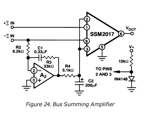
What's not immediately obvious with this topology is that the differential front end is a common base topology with "current" feedback to the emitter. The feedback resistors are the 10KΩ internal to the SSM2017.
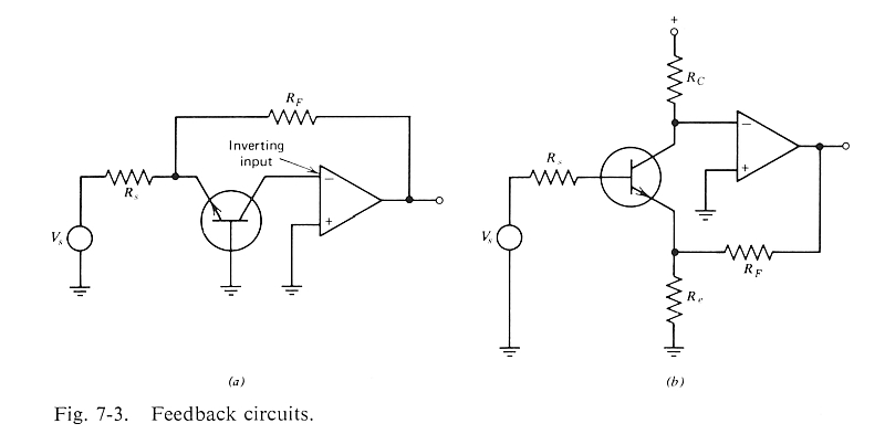
Motchenbacher and Fitchen in "Low Noise Design" show in (a) the half-circuit common base version whereas (b) is the more common topology we often call "Cohen" when made differential.
The SSM2017 app note conceptually turns the transistor on its side making it electrically a CB front end.
The question I have is in a mix amp with low source impedance and high noise gain is there an advantage to using a common base topology?
Or was this a way to get a 1nV√Hz matched diff pair and sell SSM2017s?
Last edited:
I wrote about the transamp as a common base sum amp in my 40 year old console article, but the transamp was not 1nV/rt HZ.
JR
PS sorry about your keyboard....
JR
PS sorry about your keyboard....
living sounds
Well-known member
Currently the Signetics 5534AN.The grainyness was in the following stage.
Still hear op amp differences?
If so which one did you end up using?
My vote is 5532/34.
The mixbus is no longer the weakest link. Now I'm wondering why the fader path of the rec path sounds worse than the one of the tape path. It's possible to switch those faders between the rec and tape channel by flicking a switch. The only difference between the two is that for volume control the former uses a pot (PG fader) and the latter uses a VCA(THAT2181) followed by a buffer (and two additional coupling caps on input and output). Everything before and after is exactly the same. The signal path with the VCA not only sounds better, but with the VCA trimmed has lower K2 harmonic distortion than the other one...
ruffrecords
Well-known member
Odd that the more complex route should have lower distortion. OTOH it may be that trimming the VCA cancels some distortion from the previous stage leading to an overall reduction in harmonics distortion.. This is a technique that was often used on early tube mice pres like the REDD 47.Currently the Signetics 5534AN.
The mixbus is no longer the weakest link. Now I'm wondering why the fader path of the rec path sounds worse than the one of the tape path. It's possible to switch those faders between the rec and tape channel by flicking a switch. The only difference between the two is that for volume control the former uses a pot (PG fader) and the latter uses a VCA(THAT2181) followed by a buffer (and two additional coupling caps on input and output). Everything before and after is exactly the same. The signal path with the VCA not only sounds better, but with the VCA trimmed has lower K2 harmonic distortion than the other one...
Cheers
Ian
If you can reliably hear a clearly audible difference between the two paths, there should be objective bench measurements that correlate with the perceived audible difference.Currently the Signetics 5534AN.
The mixbus is no longer the weakest link. Now I'm wondering why the fader path of the rec path sounds worse than the one of the tape path. It's possible to switch those faders between the rec and tape channel by flicking a switch. The only difference between the two is that for volume control the former uses a pot (PG fader) and the latter uses a VCA(THAT2181) followed by a buffer (and two additional coupling caps on input and output). Everything before and after is exactly the same. The signal path with the VCA not only sounds better, but with the VCA trimmed has lower K2 harmonic distortion than the other one...
Excuse me for asking this but is the polarity of both paths the same (like asking the customer if it is plugged in)? VCA circuits are typically inverting so maybe the buffer you mention is in there to flip it back into correct polarity.
I might start with a null test to attempt to quantify how large the difference is. Then compare conventional old school bench measurements like frequency response, linearity (distortion), and even S/N.
The cause will probably be the last thing you checked.

JR
living sounds
Well-known member
But it works irrespective of the previous stage, I can switch between the preceding rec and tape signal paths...Odd that the more complex route should have lower distortion. OTOH it may be that trimming the VCA cancels some distortion from the previous stage leading to an overall reduction in harmonics distortion.. This is a technique that was often used on early tube mice pres like the REDD 47.
Cheers
Ian
living sounds
Well-known member
The rec fader has higher K2 distortion, this holds true for the other channels as well. Sure, the polarity is the same. The VCA flips the phase and an inverted buffer flips it back again.If you can reliably hear a clearly audible difference between the two paths, there should be objective bench measurements that correlate with the perceived audible difference.
Excuse me for asking this but is the polarity of both paths the same (like asking the customer if it is plugged in)? VCA circuits are typically inverting so maybe the buffer you mention is in there to flip it back into correct polarity.
I might start with a null test to attempt to quantify how large the difference is. Then compare conventional old school bench measurements like frequency response, linearity (distortion), and even S/N.
The cause will probably be the last thing you checked.
JR
Last edited:
ruffrecords
Well-known member
Are you saying the input of both the VCA are switchable?But it works irrespective of the previous stage, I can switch between the preceding rec and tape signal paths...
Probably schematic of the area would help. It cannot defy the laws of physics.
Cheers
Ian
living sounds
Well-known member
No, the console allows you to switch signal paths. In the default position the rec channel goes through the smaller fader (no VCA) and the tape channel uses the big VCA fader. Press the FDR button and it gets switched around.Are you saying the input of both the VCA are switchable?
Probably schematic of the area would help. It cannot defy the laws of physics.
Cheers
Ian

living sounds
Well-known member
Well, from the schematic the paths are not really the same. I'll have to check the PCB. There are lot's of (un?)intentional errors in these schematics...
I don't see the VCA either..
To realize good fader kill I typically referenced the fader ground into the post fader diff amp.
JR
To realize good fader kill I typically referenced the fader ground into the post fader diff amp.
JR
living sounds
Well-known member
The VCA is not shown, it's a THAT2181 followed by a 5534 buffer, it goes between ST6 13/14 and ST6 19/20 (FDR send/FDR return in the schematic). It's on a different PCB and I haven't got an accurate schematic because I upgraded the VCA chip and changed a few surrounding parts to make it work properly. The problem lies not with the VCA channel but with the other one. It's the one on top (FDR2).I don't see the VCA either..
To realize good fader kill I typically referenced the fader ground into the post fader diff amp.
JR
Last edited:
living sounds
Well-known member
I've made some tests. I couldn't find a difference between the channels with a signal generator and a scope, sinewaves, squarewaves, it looks pretty much the same. However, one difference of note was that the VCA channel has a little less DC bias on the inputs and a lot less DC bias on the outputs of the fader buffer amp. There is -0.13V on the VCA channel output but -0.7V on the potentiometer channel. I don't pretend to understand the biasing arrangements on the inputs in the schematic (also drawn inacurately, I would guess), but they're clearly different. Now the polarized electrolytic output cap for the pot-only channel is oriented correctly for a negative bias, while the VCA channel indeed has the slight negative bias going into the positive side of the cap. The schematic displays it correctly.
Now I understand caps tend to perform worse with a DC bias, but in this case the bias isn't much either way and the worse performing channel actually has the cap oriented correctly.
Does anyone have an idea what the intention of the designer was with the schematic and if the caps could have anything to do with it? I upped them both to 220uF per his suggestions when I recapped the whole console.
The 5534 is a bipolar op amp with NPN input differential stage.The input bias current is 500 nA typical, and 1500 nA max... that base current flowing through a 470k resistor will drop 0.7V max 0.235V typical... this mainly informs us what direction to orient the polar capacitors.
The resistor dividers look like a crude attempt to introduce a modest + DC voltage to cancel out the voltage drop caused by the bipolar op amp's input stage base current draw pulled through the 470K resistors.
JR
PS: I understand that polar electrolytic capacitors are designed to be used with a DC bias.
living sounds
Well-known member
In both of the chains a positive voltage is added, and the orientation of the polarized caps on the input reflect this. But why the difference in orientation of the output electrolytic between the chains?The 5534 is a bipolar op amp with NPN input differential stage.The input bias current is 500 nA typical, and 1500 nA max... that base current flowing through a 470k resistor will drop 0.7V max 0.235V typical... this mainly informs us what direction to orient the polar capacitors.
The resistor dividers look like a crude attempt to introduce a modest + DC voltage to cancel out the voltage drop caused by the bipolar op amp's input stage base current draw pulled through the 470K resistors.
JR
PS: I understand that polar electrolytic capacitors are designed to be used with a DC bias.
According to Cyril Bateman's measurements, polar electrolytic caps show varying distortion depending on the make and model of the cap and the amount of bias. A non-polar electrolytic is always superior in terms of THD. That's what I will try next.
Similar threads
- Replies
- 40
- Views
- 2K
- Replies
- 57
- Views
- 6K
- Replies
- 0
- Views
- 123