You are using an out of date browser. It may not display this or other websites correctly.
You should upgrade or use an alternative browser.
You should upgrade or use an alternative browser.
Surplus store score! Collins 26c and 2x Gilfillan Bros/Bendix filters pics
- Thread starter plumsolly
- Start date


Help Support GroupDIY Audio Forum:
This site may earn a commission from merchant affiliate
links, including eBay, Amazon, and others.
plumsolly
Well-known member
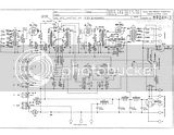
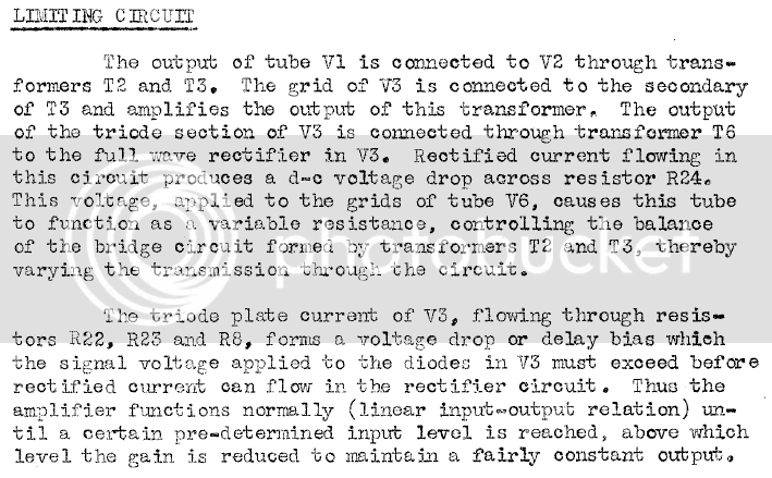
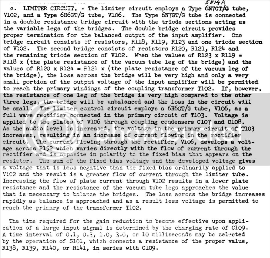
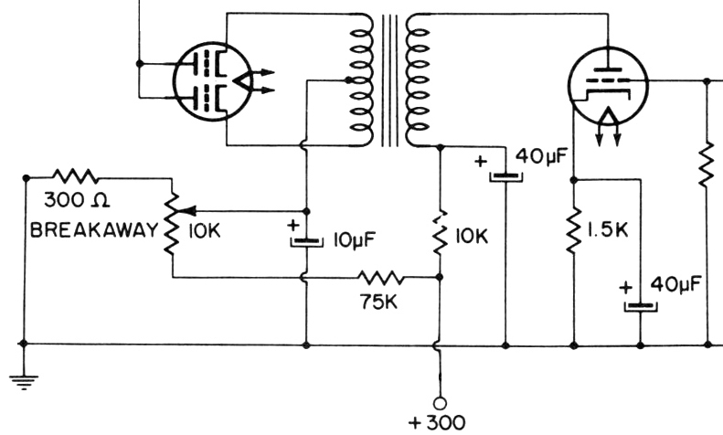
I am still working on mounting the new transformers in the case - I haven't had much time with the holidays and school - but while trying to avoid doing schoolwork lately, I have been looking at the schematic for the 26c and the 26w and trying to understand the limiter/sidechain sections and how they are different. The manuals with the schematics and theory of operation!!! are incredible resources.The way I am understanding it now is that in the 26c, the sidechain signal is pulled off of t3, amplified in the triode section of v3, fed to the rectifier in v3 through t6, and then applied to the grids of t6 thus lowering the plate resistance and creating a bridge/pad with t2 and t3. In the 26w, the principle is similar, but there is no amplification of the sidechain signal - instead the sc signal is fed to the rectifier directly and this voltage is used to modulate a bias voltage which is fed to the grids of the limiter tube, creating a bridge/pad with the plates and resistors. How am I doing so far?
Here are the relevant schematics and excerpts from the theory of operation sections. It is worth downloading the entire manuals - they are works of art and very educational.
26c:
26w:

26c:
26w:
Here are the relevant schematics and excerpts from the theory of operation sections. It is worth downloading the entire manuals - they are works of art and very educational.
26c:

26w:

26c:
26w:
in a quick skim it seems you are on it.
I would only add about side chain amplification differences. Many older limiters use the method of the 26C, where the signal splits early and is amplified in parallel with the output stage. Sometimes this is done so that limiting amount can be controlled with another pot that is separate from the amps input or output controls. In the 26C the side chain relationship is fixed, and the amps output control is after the split.
Later designs switch to the more familiar circuit where the side chain is taken after the output tubes, so greater amplification has occurred without need for a parallel stage, or an additional phase splitting transformer. Here, the side chain relationship is locked at least to the maximum gain available from the amps output stage. In some cases, you still see additional gain before the SC rectifier, but usually not. Those cases would be limiters which use relatively low output finals, like 12AU7/12BH7/etc rather than power tubes like 6V6/6K6/etc.
The Fairchild is omitted from this discussion since it's an entirely different gain staging and SC approach.
plumsolly
Well-known member
Thanks for the explanation, Doug. In the 26c, can I change the threshold by adjusting r22/r23? I don't understand how the triode section interacts with the rectifier section in the 6R7, so I am not sure how to change them to lower the threshold. Thanks, Ben
plumsolly
Well-known member
Thanks Doug. I'll give the pot a try. The thing about using the input control as a threshold is that the gain staging required to get it into limiting is on the verge of unmanageable; I have to set the input up all the way and the output at one or two steps above the bottom - it doesn't leave a lot of room to maneuver. And even with the Collins set like that, it requires a pretty high signal on the input - such that I am always in danger of overdriving the previous stage to get it there - and the output is always close to overdriving the next stage.
-Ben
-Ben


![Soldering Iron Kit, 120W LED Digital Advanced Solder Iron Soldering Gun kit, 110V Welding Tools, Smart Temperature Control [356℉-932℉], Extra 5pcs Tips, Auto Sleep, Temp Calibration, Orange](https://m.media-amazon.com/images/I/51sFKu9SdeL._SL500_.jpg)
plumsolly
Well-known member
I gave the the pot a try (with R21 connected to the wiper) and it didn't seem to have any effect as I rotated it. So I tried using the pot as a rheostat in place of R22 and that didn't do anything either. Then I tried it as rheostat in place of R23, and that seemed to do the trick. Lowering the value of the rheostat increased compression. Right now I have it all the way down (for all practical purposes, I've just jumpered over R23), and there is actually still a lot of room under the threshold, but it is definitely more manageable. Can you see any drawbacks to this approach? Thanks, Ben
I have my input set up with a modified bridging pad, and it still doesn't take much to get it into limiting. Are your sources low in output, or is something else going on?
My output is always very low as well, that's normal.
R23 rheostat sounds reasonable. Are you saying the first attempt with R21 to wiper, that the pot replaced R22 and R23? I'm gonna go dig out another circuit along these lines that has a variable threshold approach.
My output is always very low as well, that's normal.
R23 rheostat sounds reasonable. Are you saying the first attempt with R21 to wiper, that the pot replaced R22 and R23? I'm gonna go dig out another circuit along these lines that has a variable threshold approach.
Okay, not the same, but worth a look. Here the threshold is set by the bias on the CT of the transformer, and the time constants are out of view downstream from the double diode.
The 26C TC's are at the CT, with that being the direct feed point for the CV. I think bias can only come from the cathode potential.
The 26C TC's are at the CT, with that being the direct feed point for the CV. I think bias can only come from the cathode potential.
plumsolly
Well-known member
emrr said:Are your sources low in output
No - either whatever my sound card can push before clipping, or I'll sometime run through a channel on my console as a line driver to get more level.
emrr said:or is something else going on?
Now I'm wondering. You say you have a pad on your input?
emrr said:Are you saying the first attempt with R21 to wiper, that the pot replaced R22 and R23?
Exactly.
Is the threshold in the 26c just cathode-grid feedback in the triode section V3? If so, I don't understand why the pot didn't work. What is the relationship between the diode section and the triode section of V3 - are they separate circuits in the same tube, or does what's happening in the triode section effect what's happening in the diode section?
emrr said:Okay, not the same, but worth a look.
What circuit is this?
Thanks for all your help Doug, and merry Christmas!
Ben
the threshold appears to be the cathode bias amount.
Mine has the built in bridging pad connected, and I think I raised the value of it even higher.
That is part of an RCA Photophone de-esser circuit that's in the Audio Cyclopedia.
Mine has the built in bridging pad connected, and I think I raised the value of it even higher.
That is part of an RCA Photophone de-esser circuit that's in the Audio Cyclopedia.
plumsolly
Well-known member
emrr said:the threshold appears to be the cathode bias amount.
Ok - that makes sense now - the diode section shares a common cathode with the triode section. But shouldn't making R22 smaller lower the threshold then? I am wondering if something funky is going on around there that might explain the unpredictable behavior of that pot as well as my seemingly heightened threshold. Bad replacement T6, maybe? I have an extra 6R7, too. I'll look around that area.
Best, Ben
Lowering r22 will also change the triode bias, and the linked bias of the diode and triode sections may be canceling the desired effect. I've not through that one through yet.
It's also changing the cathode/grid relationship across r21. I've seen the same conditions in some other limiters, with the 6R7 grid resistor returned to a voltage division on the cathode rather than to ground. On one limiter, I've seen some units like this, and some other revisions with the grid R to ground instead. I confess to having not grappled and grasped this distinction yet.
It's also changing the cathode/grid relationship across r21. I've seen the same conditions in some other limiters, with the 6R7 grid resistor returned to a voltage division on the cathode rather than to ground. On one limiter, I've seen some units like this, and some other revisions with the grid R to ground instead. I confess to having not grappled and grasped this distinction yet.
plumsolly
Well-known member
emrr said:Lowering r22 will also change the triode bias, and the linked bias of the diode and triode sections may be canceling the desired effect.
That's interesting. But lowerig r23 should be having the same effect on the triode bias...? So I guess it also must have something to do with the cathode/grid relationship across r21 as well? I would be interested to see other configurations in similar circuits.
Thanks as always Doug, and happy New Year - Ben
plumsolly
Well-known member

Pretty similar around the 6R7. I might try these resistor values and see what it does to the threshold.
Best, Ben
plumsolly
Well-known member
I changed some resistor values around the 6R7 to the values RCA used: R21 to 100k, R23 to 3.3k, and R22 to 1k. The threshold is now at a pretty usable place. I am still not sure what exactly is happening, besides that increasing the grid resistor is increasing the amplification of the triode stage, but I am getting the results I want so I am pretty happy. I think I have decided to put a hard bypass switch and attack and recovery controls on a separate 2u panel and then I'll be ready to quit meddling and just enjoy it. I'll post pics when I finish it. All the best, Ben
Cool experiment.
I may be wrong, but I think the bias tap point of r22/23 sets a different grid bias that the typical method with grid resistance to ground, bias solely from the cathode elevation. So you are changing the operating point via cathode bias (r22/23 combo) and the additional grid bias. R21 grid resistance feeds a high Z grid, so no appreciable load there, and bias voltage at r22/23 should be pretty much the same on both ends of R21, with R21 acting as grid load and isolation. Did you try leaving R21 as 500K, and notice any difference? I wouldn't expect much.
I may be wrong, but I think the bias tap point of r22/23 sets a different grid bias that the typical method with grid resistance to ground, bias solely from the cathode elevation. So you are changing the operating point via cathode bias (r22/23 combo) and the additional grid bias. R21 grid resistance feeds a high Z grid, so no appreciable load there, and bias voltage at r22/23 should be pretty much the same on both ends of R21, with R21 acting as grid load and isolation. Did you try leaving R21 as 500K, and notice any difference? I wouldn't expect much.
plumsolly
Well-known member
emrr said:Did you try leaving R21 as 500K, and notice any difference? I wouldn't expect much.
With r21 left at 500k, lowering r23 increased compression.
It seems like it would make sense for the threshold to be pretty high for the intended application; if the purpose was to prevent your transmitter from blowing up, you probably wouldn't want limiting to engage until the signal was really loud, right? But I don't understand why our two units have seemingly different thresholds. I was wondering if it had to do with different revisions, but I just went through the replacement parts list for the 26c-1 and the 26c-2 and it doesn't seem like there is a great deal of difference between them with the exception of the transformers. I have that replacement t6, but it is 15k:80k instead of the 20k:80k of the original, so it it should actually provide me with a little more gain in the side chain. Hmmm, a mystery...
Best, Ben
thejoerusso
Member
- Joined
- Mar 27, 2009
- Messages
- 17
Hey guys, I'm finally back playin with this thing. So I've got the rewound transformer back from Doc and installed. The unit now works great as an amplifier, the response has come back. The bad news is it now does not compress at all. GR meter indicates compression, but no affect on the audio. To clarify, it did compress before, just with very poor freq response. I'm checking things over again, but nothing was touched while the coil was away. I measured both coils with an LCR meter, the rewound unit shows noticeably less inductance on all windings.  I am admittedly not sure if I'm interpreting/measuring properly, but there is still a difference between the two coils. Is there a better way to be measuring the inductance here?
Thanks as always,
Joe
I am admittedly not sure if I'm interpreting/measuring properly, but there is still a difference between the two coils. Is there a better way to be measuring the inductance here? Thanks as always,
Joe
plumsolly
Well-known member
Hey Joe - When I subbed my T6 for my T2 I mixed up the way that the T3 and T2 secondaries connected together - it's tricky because all the leads are green - and it didn't compress. You might try reversing the way you have the secondaries connected together and see if that helps. I hope that makes sense.
Good Luck,
Ben
Good Luck,
Ben