You are using an out of date browser. It may not display this or other websites correctly.
You should upgrade or use an alternative browser.
You should upgrade or use an alternative browser.
Surplus store score! Collins 26c and 2x Gilfillan Bros/Bendix filters pics
- Thread starter plumsolly
- Start date


Help Support GroupDIY Audio Forum:
This site may earn a commission from merchant affiliate
links, including eBay, Amazon, and others.
I measured both coils with an LCR meter, the rewound unit shows noticeably less inductance on all windings. I am admittedly not sure if I'm interpreting/measuring properly, but there is still a difference between the two coils. Is there a better way to be measuring the inductance here?
Regardless of meter inaccuracies over 'true' L value I would think that your measurements still point to a valid difference. I mean, even if measuring with an inductance bridge gives a different number the relative values between the two should remain essentially the same should they not? Have you been able to measure response with the rewound iron yet?
thejoerusso
Member
- Joined
- Mar 27, 2009
- Messages
- 17
lassoharp said:I measured both coils with an LCR meter, the rewound unit shows noticeably less inductance on all windings. I am admittedly not sure if I'm interpreting/measuring properly, but there is still a difference between the two coils. Is there a better way to be measuring the inductance here?
Regardless of meter inaccuracies over 'true' L value I would think that your measurements still point to a valid difference. I mean, even if measuring with an inductance bridge gives a different number the relative values between the two should remain essentially the same should they not? Have you been able to measure response with the rewound iron yet?
Agreed. I've checked the connections, but I will double check again with fresh eyes..
plumsolly
Well-known member
I have been using, liking, fiddling with, and getting to know my 26c for the last year. Just this week I was looking at the frequency response a bit (you can see a plot on page 5) and I discovered that the dip just below 10k comes from the input transformer - a UTC HA 101X. I am using a 10K:600 pad on the input, but the dip is there when the pad is bypassed. If I feed the grid of V1 with a signal generator there is no dip. Could the dip be the back end of a steep high frequency rise above it - one that can't be seen because of the bandwidth of the rest of the device? Looking for any suggestions about what to look at.
Thanks,
Ben
Thanks,
Ben
Sounds like the typical UTC split winding resonance/cancelation. 101 is meant for PP, if I remember right? Try wiring the secondary in parallel, may improve response, and likewise will lower input gain. Gates would sometimes wire PP split winding transformers for SE purpose using only half of a sec, and leave the other side floating. Looks very wrong on paper, plots better.
plumsolly
Well-known member
That sounds like it, Doug. I didn't realize there were restrictions on putting secondaries in series for SE. Strictly a UTC thing? Some kind of hum-bucking deal? If I put the secondaries in series, I will loose 3db (which I could actually use, but whatever for now). Are there other noise penalties for giving a lower impedance to the grid? It looks like the UTC line to single grids are mostly 50 or 60K secondaries anyhow. I will get in there and try some stuff - no walk in the park to get at the transformers in these.
Best,
Ben
Best,
Ben


![Soldering Iron Kit, 120W LED Digital Advanced Solder Iron Soldering Gun kit, 110V Welding Tools, Smart Temperature Control [356℉-932℉], Extra 5pcs Tips, Auto Sleep, Temp Calibration, Orange](https://m.media-amazon.com/images/I/51sFKu9SdeL._SL500_.jpg)


plumsolly
Well-known member
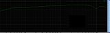
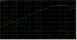
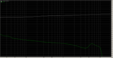
Ok - I ran some tests and here are the results:
Here is a more detailed view of the ha101x input with secondaries in series:
Here is ha101x with only one secondary winding connected:
Here is ha101x with secondaries in parallel:
Here is an Edcor 10k:10K:
Here is a UTC ha108x 500:500:
Here is unbalanced straight into grid of V1 with 100k grid R:
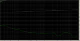
A few observations:
Leaving one winding floating didn't work.
Secondaries in // looks ok - I lose that 3db though.
The Edcor sucks - not sure what that's about. Update - It was broken.
The ha108x looks just like the no-transformer plot - that's pretty nice - obviously I lose any gain from the transformer.
So I guess I need to find something near 600:80k that performs like the ha108x. Any ideas?
These are all with the limiting circuit out.
In any case I think that 500:500 plot looks pretty nice.
Thanks, Ben
Here is a more detailed view of the ha101x input with secondaries in series:

Here is ha101x with only one secondary winding connected:

Here is ha101x with secondaries in parallel:

Here is an Edcor 10k:10K:

Here is a UTC ha108x 500:500:

Here is unbalanced straight into grid of V1 with 100k grid R:

A few observations:
Leaving one winding floating didn't work.
Secondaries in // looks ok - I lose that 3db though.
The Edcor sucks - not sure what that's about. Update - It was broken.
The ha108x looks just like the no-transformer plot - that's pretty nice - obviously I lose any gain from the transformer.
So I guess I need to find something near 600:80k that performs like the ha108x. Any ideas?
These are all with the limiting circuit out.
In any case I think that 500:500 plot looks pretty nice.
Thanks, Ben
The Edcor sucks - not sure what that's about.
Sure looks it. What was your source impedance for that plot?
plumsolly
Well-known member
Hey Lasso - In all cases, the signal came from 320 ohm Lucid converters. The ha101x tests were done with a 10k:600ohm U-pad in front. All the others came straight from the Lucid.
Best,
Ben
Best,
Ben
I'd estimate the HA-101 500r winding to probably have about 13 to 20H and assuming lack of L is cause of Edcor roll off that would seem improbably low for a '10K' winding, to be below 13H. Must be something else going on. Hopefully Doug will know.
Good set of sweeps Ben.
Did you get to listen to program material for the half winding - other half left open connection? Just curious if it sounds as boosted as it looks.
Good set of sweeps Ben.
Did you get to listen to program material for the half winding - other half left open connection? Just curious if it sounds as boosted as it looks.
plumsolly
Well-known member
I did not listen to that one. Regarding the L of the Edcor, you'd think that this would be the type of situation it would be designed to perform in, albeit with a lower load on the secondary maybe... Maybe mine is broken?
plumsolly
Well-known member
A couple of modern replacement candidates:
http://www.lundahl.se/pdf/7905.pdf - looks like 600:75K which is just about perfect, not a very convenient package, though.
http://www.lundahl.se/pdf/1922.pdf - Lundahl version of UTC LS-10. 600:50k.
http://www.sowter.co.uk/specs/9062.htm - 600:40k.
http://www.sowter.co.uk/specs/1009.htm - Sowter version of UTC A-10. 600:50k - It looks like the response would suffer with a 100k load, which I am tied to.
I can't see any of those sweeps, they are teeny tiny here and when clicked on, and again at photobucket.
The restriction is with some transformers designed for PP use, they don't act well when connected SE with both windings. All UTC I've looked at behave better in PP than in SE, including those meant for SE.
The restriction is with some transformers designed for PP use, they don't act well when connected SE with both windings. All UTC I've looked at behave better in PP than in SE, including those meant for SE.
plumsolly
Well-known member
Hey Doug - try looking at those sweeps in Chrome. Not sure what's going on with that.
Best,
Ben
Best,
Ben
Mike Cleaver
Well-known member
Just stumbled on this thread while researching some other Collins broadcast gear.
I hope you've replaced all those selenium rectifiers visible in the initial run of pictures you posted.
We started replacing all of those back when silicon diodes became available.
Just make certain to measure the voltage being provided at the output and adjust your new silicon bridge output to get the same voltage after removing the seleniums.
Those things are dangerous and can release a noxious gas when they fail.
The UTC looks fine for an accurate replacement part, either way. I might wire parallel, I might go series as you have it, depending on which my ears like. If you want better in a replacement way, it can certainly be had. Parallel is reasonably close to the real deal. I have heard many cool sounding amps with the notch of series connection, and the only thing wrong is worrying about the look of a plot, so long as your ears like it. Dave's clone 26C does the 26C gain reduction thing reliably, but it doesn't sound like it, and that's entirely in the unique response of the original. You lose something, you gain something.
plumsolly
Well-known member
Hey Mike - You are looking at the guts of one of those filters, which I actually have not done anything with, except to sell one of them. I will definitely keep that in mind if I ever have a go at the one I have left.
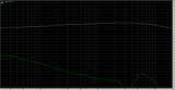
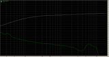
Here is another plot to chew on. This one is the Ha-108x with a .03uf cap in series with 20k.
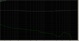
It's pretty darn flat. I listened to it for a while today and was really liking it. Not sure yet if the response is affected by where the input pot is at. Have to do some more tests before I decide what to do, but I am encouraged by the plots and sound.
Best,
Ben
Can you get compression?
Your Edcor is probably broken; just a guess. That almost looks like an open winding, with only leakage passing, but I'd expect an even sharper shape. Did you try terminating sec with 10K?
Will that program make plots scaled to something more meaningful, like +/-12? -63 to +21 is pretty dang expanded, and I don't believe what it's saying below 30 Hz. Is Hz resolution quoted? That drastically affects low frequency plot shape below 50.
plumsolly
Well-known member
Hey Doug
Yeah it is compressing - I lowered the threshold a good deal by eliminating that bias voltage on the diode section of the 6R7 and raising the gain of the triode section of the 6R7. I am also not using the bridging pad for these tests.
I did not try loading the Edcor - could be the issue.
I am using Rightmark, and I am not totally sure it scales. Will check the hz resolution. I have a couple of other programs I can compare results with.
Best,
Ben
plumsolly
Well-known member
I just hooked up the signal gen and tested the response according to the output meter on the 26c and it bears out the computer test, more or less. From a 0dB reference at 20hz it went to -2.5db at 500hz and then back up a little toward 20K, but not back up quite as much as computer plot shows ...
Best,
Ben
Best,
Ben