Swinging Inputs EQ Math (Series Resonance)

GroupDIY Audio Forum

Help Support GroupDIY Audio Forum:

This site may earn a commission from merchant affiliate links, including eBay, Amazon, and others.

OneRoomStudio

Well-known member
GDIY Supporter
Joined
Jul 8, 2004
Messages
831
Location
Minneapolis, MN, USA
Trying to wrap my head around the math here, and making sure I'm not missing something. In a 'swinging input' EQ like the API 553:
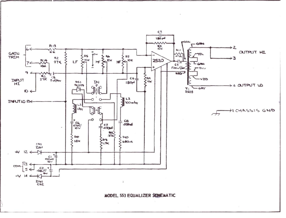
api-553.png


The low band is a 1H inductor, 47uF capacitor, and 1.8K resistor in series. By my calculations, the resonant frequency would be 23Hz, with a bandwidth of ~290Hz. I'm guessing this was done to make a pseudo-shelf control - the dip starts at around 165Hz and acts like a shelf in the audible band.

It seems like it would be a lot easier to use something like a 100mH inductor, a 100uF cap, and a 120R resistor. That would yield a center frequency of 50Hz, and with bandwidth of ~190Hz, which would have the dip start at around 145Hz, and look fairly similar below that. It would cut slightly less between 20Hz and 50Hz than the original, but only marginally so, and would use a much easier to find 100mH inductor.

Am I missing some important point here?

The mid band make sense to me. A 100mH inductor, 39nF cap, and 680R resistor yield a center frequency of around 2.5KHz, with a bandwidth of about 1080Hz - pretty sensible.

The top band has me confused too though. Because this is a simple RC band, rather than an RLC band, I figured I should use the standard RC  equation, f = 1/(2π * R * C) - but with C = 33nF and R = 1300, that gives me a frequency of  3710Hz, which can't be right. This is clearly not a standard RC low pas circuit anyway. How do I calculate the frequency and bandwidth of the RC high band?
 
OneRoomStudios said:
The low band is a 1H inductor, 47uF capacitor, and 1.8K resistor in series. By my calculations, the resonant frequency would be 23Hz, with a bandwidth of ~290Hz. I'm guessing this was done to make a pseudo-shelf control - the dip starts at around 165Hz and acts like a shelf in the audible band.

It seems like it would be a lot easier to use something like a 100mH inductor, a 100uF cap, and a 120R resistor. That would yield a center frequency of 50Hz, and with bandwidth of ~190Hz, which would have the dip start at around 145Hz, and look fairly similar below that. It would cut slightly less between 20Hz and 50Hz than the original, but only marginally so, and would use a much easier to find 100mH inductor.
You've answered your own question. The designers at API wanted too make sure the low band extended to the lowest limit. What about VLF that would not be tamed by the LF control?

The top band has me confused too though. Because this is a simple RC band, rather than an RLC band, I figured I should use the standard RC  equation, f = 1/(2π * R * C) - but with C = 33nF and R = 1300, that gives me a frequency of  3710Hz, which can't be right. This is clearly not a standard RC low pas circuit anyway. How do I calculate the frequency and bandwidth of the RC high band?
Shelving EQ's do not follow the same math than bells. A HF control specified as -15dB ar 10kHz for example, starts Boost/cut at about 1kHz. The specified boos/cut is from 10kHz to VHF.
 
abbey road d enfer said:
Shelving EQ's do not follow the same math than bells. A HF control specified as -15dB ar 10kHz for example, starts Boost/cut at about 1kHz. The specified boos/cut is from 10kHz to VHF.

That makes sense. Can you shed some light on which math a shelving filter does use? According to the sources I can find (http://www.linkwitzlab.com/filters.htm#5), Fz (-3dB down point) should still follow the equation  f = 1/(2π * R * C). What am I missing here?

Thanks for the help!
 
The problem with shelving is that there is no agreement on how to define the frequency,  every manufacturer does it differently. It can be 1dB, 1.5dB, 2dB, 3dB etc  down at full boost / cut.

So it's hard to define mathematically when there is no standard.
 
> low band is ..... 1.8K resistor
> easier to use something like ... 120R resistor.


The peak gain is something like 10k/r. 10k/1.8k is a mild gain. 10k/120r is a huge gain.

Yes the smaller coil is cheaper. But to keep useful audio effects, all the other parts have to be in proportion. Maybe 1k NFB and 1k pots. This may strain the opamp. It puts 10x the current in the coil, negating much of the cost-advantage of lower L.
 
PRR said:
> low band is ..... 1.8K resistor
> easier to use something like ... 120R resistor.


The peak gain is something like 10k/r. 10k/1.8k is a mild gain. 10k/120r is a huge gain.

Yes the smaller coil is cheaper. But to keep useful audio effects, all the other parts have to be in proportion. Maybe 1k NFB and 1k pots. This may strain the opamp. It puts 10x the current in the coil, negating much of the cost-advantage of lower L.

I knew I was missing something! Thanks PRR, I had completely neglected to consider the gain of the opamp. The large coil makes a lot more sense now.

Any insight into the high band?
 
OneRoomStudios said:
That makes sense. Can you shed some light on which math a shelving filter does use? According to the sources I can find (http://www.linkwitzlab.com/filters.htm#5), Fz (-3dB down point) should still follow the equation  f = 1/(2π * R * C). What am I missing here?

Thanks for the help!
First, the usual math for filters does not work fully with EQ's. The reason is filters have asymptotic response to zero (minus infinity in dB), when EQ's have an asymptotic response to unity (0dB). So everything about Q is twisted; just think how you can use the -3dB definition with an EQ that is set at 2dB boost, doesn't make sense, does it?
Just the same, a shelf EQ actually applies two filters to the signal, one that defines the turnover and one that defines the plateau. This may not seem obvious when seeing the small component count, but it's actually the case.

An active EQ works on the principle that a portion K (that can be positive or negative and maybe >1) of the signal is fed in addition to the signal via a filter.
Let T be the transmittance of such filter, the resulting output is 1+K.T.
Let's take the simple example of a HPF, which transmittance is s/(s+1), the output becomes (1+K)[s/(s+1)} or [(1+K)s+1]/(s+1)
You see that, if the denominator is the same polynom as that that defines the basic HPF, the numerator is a different polynom, defining a quite different turnover frequency.
 
Thank you for diving into that. I'm slowly learning more about the transfer functions of these circuits.

I'm still having trouble understanding how to calculate new values for the high band of the 553 circuit though. Is there an equation I can use that would give me a rough ability to choose alternate values for R and C to change the effected frequencies? Obviously, a smaller cap or smaller resistor  will push the shelf up, but how do I determine what the "audible" or "equivalent" frequency is? Did API just make up the "10kHz" value they assigned to the high band? If not, how did they arrive at that number?
 
OneRoomStudios said:
Thank you for diving into that. I'm slowly learning more about the transfer functions of these circuits.

I'm still having trouble understanding how to calculate new values for the high band of the 553 circuit though. Is there an equation I can use that would give me a rough ability to choose alternate values for R and C to change the effected frequencies? Obviously, a smaller cap or smaller resistor  will push the shelf up, but how do I determine what the "audible" or "equivalent" frequency is? Did API just make up the "10kHz" value they assigned to the high band? If not, how did they arrive at that number?
See attachment. It could be described as +/- 12dB @10kHz or +/-13dB@20kHz. Since most people don't hear 20k, they'd rather have a usable info instead of relying on their dogs.  :)
It could also be described as +/-6dB at 2kHz, which would be true but wrong. It is customary to use a frequency close to the maximum Boost/cut, but since the curves are asymptotic, the actual maximum may be elusive.
it's customary to specify Baxandall's at about 80-100Hz for LF and 8-12k for HF.
When specifying multiple turnover EQ's, one would take a starting point at one of these "standard" frequencies and extend to the other frequencies.
 

Attachments

  • Bax HF response.jpg
    Bax HF response.jpg
    38.5 KB
OneRoomStudios said:
but how do I determine what the "audible" or "equivalent" frequency is?
See in this attachment how these two could be both described as +/-12.5dB @10kHz, but they are obviously different.
The one in light blue shows that it has not started to plateau at 10kHz (it is actually capable of +/- 30+dB at 100kHz), so quaoting it as +/-12.5dB@10kHz is a very narrow description of its capabilities.
 

Attachments

  • Bax HF different.jpg
    Bax HF different.jpg
    33.5 KB
Thanks again for helping to explain this to me!

I understand how the curves can be different, and yet both described as "+/-12dB @ 10KHz," but there must be some way of determining the frequency at witch the curve begins to plateau without having to plot it. Describing the plateau frequency seems to be a reasonable way of describing the shelf frequency. Is there an equation to determine the frequency at which the curve begins to plateau?
 
OneRoomStudios said:
Thanks again for helping to explain this to me!

I understand how the curves can be different, and yet both described as "+/-12dB @ 10KHz," but there must be some way of determining the frequency at witch the curve begins to plateau without having to plot it. Describing the plateau frequency seems to be a reasonable way of describing the shelf frequency. Is there an equation to determine the frequency at which the curve begins to plateau?
No, the usual -3dB definition doesn't work. How would you determine the plateau on an EQ that has only +/-3dB boost/cut? I know it's not aparticularly typical but it exists.
There are softwares that are capable of evaluating mathematically what the eye (and brain) detect almost instinctively, but no easy math.
 
I know this is an old topic, but I am looking at the design of an EQ of this type, so I thought I would add a couple of comments,

The resistor in series with the capacitor in the HF section sets the  max available boost/cut for that section. If you want to change the frequency but not the amount of available boost/cut (the normal case) then all you need do is change the value of the capacitor. The value of the capacitor is inversely proportional to the frequency. So if you want to double the frequency you half the value of the capacitor.

It is common to approximate these curves by straight lines (for analytical purposes rather then for defining the plateau frequency). HF boost begins at 6dB per octave at some frequency and the returns to horizontal at the frequency determined by RC. Since the plateau always occurs at the same frequency irrespective of the setting of the pot, different boosts are obtained by altering the frequency at which the 6dB per octave boost starts. The frequency is determined largely by the pot. The more the boost, the lower the frequency at which it starts.

Cheers

Ian
 
Those are great comments Ian. I had observed some of that but I wasn’t sure what I was looking at. This clears a lot of it up for me. Would you do a differential input tube gain stage?

I like swinging input EQ’s. I didn’t realize the QE310 was swinging input because it’s discrete and I didn’t put it together. They also look semi parametric on the faceplate so it wasn’t a clue. I love those and others.
 
Gold said:
Those are great comments Ian. I had observed some of that but I wasn’t sure what I was looking at. This clears a lot of it up for me. Would you do a differential input tube gain stage?
It is something I am considering.
I like swinging input EQ’s. I didn’t realize the QE310 was swinging input because it’s discrete and I didn’t put it together. They also look semi parametric on the faceplate so it wasn’t a clue. I love those and others.
So called swinging EQs appear to use the same basic topology as graphic EQs so making one semi parametric is not hard.

Cheers

Ian
 
A number of years ago Fred Forssell put out a paper making the case for a swinging input EQ.
https://www.forsselltech.com/media/attachments/EQ1A.PDF

He designed the Mellenia Media EQ which is generally well regarded in mastering circles. It looks like a parametric EQ.
 
Yes, that schematic is essentially the same as that of a graphic equaliser. It has the interesting property that as the amount of boost is reduced the bandwidth widens.

Cheers

Ian
 
I was toying with the idea of using wirewound ten turn pots and counter dials in an eq ,  it would allow precise recall of eq settings with a simple 3digit short code 0-9.99,  but require a numerical table to opperate in db cut/boost terms  , Does that sound completely mad? :D 
 
Tubetec said:
I was toying with the idea of using wirewound ten turn pots and counter dials in an eq ,  it would allow precise recall of eq settings with a simple 3digit short code 0-9.99,  but require a numerical table to opperate in db cut/boost terms  , Does that sound completely mad? :D
The amount of boost or cut is not proportional to the resistance. You could indeed write a table. Anyway, do you set an EQ according to the amount of dB or to what you hear?
 
Tubetec said:
I was toying with the idea of using wirewound ten turn pots and counter dials in an eq ,  it would allow precise recall of eq settings with a simple 3digit short code 0-9.99,  but require a numerical table to opperate in db cut/boost terms  , Does that sound completely mad? :D

Sounds weird to me but things I do are weird to others. If the EQ is for personal use and it makes sense to you there is nothing wrong with it. If it's for others I think you would get pushback. The main reason I think it's weird is that the number displayed is the only indication of pot position. You can't glance at the line and know the approximate setting.
 
Back
Top