THAT (was Fet) Compressors

GroupDIY Audio Forum

Help Support GroupDIY Audio Forum:

This site may earn a commission from merchant affiliate links, including eBay, Amazon, and others.
I have a limiter based on the Leach at the studio where I master and it can be very effective.  In fact, just last week a forum friend built the Leach circuit and we had a quick shootout.  It won't beat a modern hi end plug in limiter but it can be useful and I've used it on masters as recently as just last week.
 
The Leach circuit makes complete sense as an educational exercise to showcase sundry circuit design blocks.

I still find the JFET gain element a little too economic for my taste in the context of that much glue circuitry. There were other gain element choices besides THAT/ VCAs  (THAT was only started in '89 to merchandise DBX IP).  I repeat with the linearization trick the JFETs should not introduce audible artifacts, so sound quality depends on the side chain. For a one-off do whatever floats your boat.

A great deal of work has been done on broadcast limiting (to prevent transmitter saturation) with hard clippers often involved to manage brief transients, somewhat different from general compression for loudness.

JR

PS: I do not want to sound overly harsh... There is a different focus between academic and commercial designs. I have followed Leach's work over the years for his multiple useful insights. He published a brief paper about rise-time limiting power amps that was brilliant (IMO), but apparently few read it or got it, continuing to spec amplifier slew rates for decades after that (perhaps to satisfy customers who wanted to see slew rates not rise times).
 
> the JFET gain element a little too economic for my taste
> with the linearization trick the JFETs should not introduce audible artifacts


You seem to be arguing both sides of the debate? It isn't audibly cheap, it just doesn't cost enough? And a total parts-cost around $3 (busy DIY prices) to do what Big Brands sell fro $99-$999 and up?

> broadcast limiting (to prevent transmitter saturation) with hard clippers

This is in the bigger paper. There is slow AGC, fast limit, preemphasis, limiting on that, and finally a diode clipper before the deemphasis. This is fully FCC-happy. It won't be the LOUDEST signal in town, but student radio is a different world than W-ROK or K-RAP commercial radio. I did not see stereo linking, so there could be oddness especially on non-traditionally tracked pieces.

We can picture a bit of H&P and Dean Terman. The teacher set a problem, the students worked it out, and then conceivably the GT students could have gone on to add the missing frills in a garage shop.
 
JohnRoberts said:
I repeat with the linearization trick the JFETs should not introduce audible artifacts, so sound quality depends on the side chain.
The main issue with FET's is the necessary compromise between level and distortion. It is impossible with them to achieve the VCA's typical performance of -90dBu noise/0.01% THD.
This level of performance may not be absolutely necessary, but not having to worry about it gives the designer more time to focus on all the other aspects.
One has to accept more noise or more distortion with FET's. Indeed, as in every dynamics processor, the side-chain must be the subject of extreme attention.
 
abbey road d enfer said:
Indeed, as in every dynamics processor, the side-chain must be the subject of extreme attention.
What sets M. Leachs circuit apart from others seems to be the timing cap being fed by a current source .


L´Andratté said:
What sets M. Leachs circuit apart from others seems to be the timing cap being fed by a current source .
There is a  great deal of different art covering side chains... A current fed capacitance is far from unique and generally not that desirable... A simple RC will attack faster the larger the difference and slower the less the difference (exactly what you want for less gain modulation to steady signals).  A fixed current will slew at a constant rate no matter how far it has to go.

Lots of subtleties (like what is the gain law...?). VCA compressor respond differently to side chain rate of change, than OTAs, and JFETs are yet different again.

FWIW many designers claim their way is best.  Of course it is.  ;D Some engineers using log responding VCAs argue that linear dB per unit time side chain ramps are best... (yawn).

JR

PS: At least we are discussing side chains... more important than gain elements (IMO), but it can get far more complex than this .
 
JohnRoberts said:
Some engineers using log responding VCAs argue that linear dB per unit time side chain ramps are best... (yawn).
I have a couple of plug-ins that give the choice of linear vs. log release; in most circumstances I fail to hear a significant difference. I must be deaf.
 
abbey road d enfer said:
I have a couple of plug-ins that give the choice of linear vs. log release; in most circumstances I fail to hear a significant difference. I must be deaf.
+1  I did an auto-fade in a console master section because i could (there was a VCA in the path). I made the fade linear dB/sec again because I could.

Back in the 80's I killed a lot of brain cells tweaking dynamics processors . The hard part is making them fast, but not so fast they add audible distortion, and slow (very slow) for small level changes. If you think about it, too aggressive of a side chain will distort a LF sine wave first on the rising edge(s) of the sine, then again on the falling edges... Too slow and the signal clips, burps and farts,  waiting for the gain reduction to catch up and remove boost after level changes.

There are numerous techniques to make dynamics processing as transparent as possible, some rely upon psycho-acoustic phenomenon , like masking (time masking, level masking, and even frequency masking), etc. Don't expect to find simple answers for complex problems (aka magic) and look out for the mythology that surrounds this field of design too (one of my pet peeves is hyping the virtues of RMS,  but let's not go there today.)

JR 
 
JohnRoberts said:
+1  I did an auto-fade in a console master section because i could (there was a VCA in the path). I made the fade linear dB/sec again because I could.
All designers occasionally allow themselves a little bit of fancy; lab life would be boring without it.
 
I've been playing with the leach circuit for a bit and I like what it does but am not 100% satisfied with it. Whats neat about it, is how you can completely turn off the fet and distortion becomes a non issue when its not compressing. But yes, when even limiting a couple db's, distortion at 100hz and 10K can rise way into the whole numbers. The leach circuit is also nice because the fet is working on a unity gain inverting amp. I was able to get 23db through that amp stage with the fet hanging off it (turned off) and .00XX% distortion. (+/-20v rails). That was usueful to me just because it gave the option of a decent high output signal path when not limiting.

I just ordered a couple of THAT analog engine chips to play around with. John I'm heeding your suggestion of a VCA being the better route for a limiter.

John what do you think of the THAT design notes for limiters?

http://www.thatcorp.com/datashts/dn00A.pdf

You don't think the Lin/Log thing matters in the side chain? Why would THAT go through so much trouble to put the RMS detector in the analog engine chips? They seem to think its pretty important for VCA cv. They also seem to favor feed forward in most of they're design notes, which makes me uneasy...

cheers,
Ian


bluebird said:
I've been playing with the leach circuit for a bit and I like what it does but am not 100% satisfied with it. Whats neat about it, is how you can completely turn off the fet and distortion becomes a non issue when its not compressing.
Yes a useful characteristic...  Many limiters that are only operating when signals are too loud already can get away with less than pristine distortion.

Back in the '80s I designed a quad limiter/noise gate  Using OTAs in parallel with unity gain inverting op amp feedback resistors... When the path wasn't limiting or noise gating, my distortion and noise was below residual on a soundtech (bench distortion analyzer  from back then).  The path performance was arguably better than a VCA, especially how VCAs were 30+ years ago.

The very widely used Peavey DDT clip-limiting is based on a OTA and there are probably millions of them out in the world on peavey power amps. Out of the circuit below clipping, so clean and thrifty.
But yes, when even limiting a couple db's, distortion at 100hz and 10K can rise way into the whole numbers.
The distortion cancelling trick can help, but using JFETs for limiting at high signal levels means you are hitting them with decent voltage swing that they don't like. You can scale down the signal to reduce distortion but that will impact S/N. Modern low noise op amps might help, but I am not a fan of JFETs for limiters. (I have used them in (cheap) noise gates but then they are working on low level signals. 


The leach circuit is also nice because the fet is working on a unity gain inverting amp. I was able to get 23db through that amp stage with the fet hanging off it (turned off) and .00XX% distortion. (+/-20v rails). That was usueful to me just because it gave the option of a decent high output signal path when not limiting.

I just ordered a couple of THAT analog engine chips to play around with. John I'm heeding your suggestion of a VCA being the better route for a limiter.
To be clear VCAa are better for compression or whenever the primary audio path is through the gain element. The modern VCA is really quite good. A shame actually that they finally get them this good when analog audio is in decline.  ???

OK for a best of the best path performance limiter, I will share something I came up with only a few years ago... The engineer I gave this too is now melting solder up in the sky (RIP) so he won't mind.

Imagine using the THAT vca as subtractive in the feedback path of a unity gain inverting op amp. Now when not limiting we again have the performance of a single op amp. But for limiting we crank in more negative feedback. At -6dB cut we have the performance of a VCA running at -6dB. For -20db of cut the VCA is running at =.9x .  I never used this but my friend ran it up on the bench and talked about putting it into one of his products. Their customers would never notice the limiter was that good, because everything they did was that good. 8)
John what do you think of the THAT design notes for limiters?
The THAT website design notes are worthwhile reading (all of them).
http://www.thatcorp.com/datashts/dn00A.pdf

You don't think the Lin/Log thing matters in the side chain?
When using VCAs that respond to log gain control, it is very useful to operate in log domain.  My one patent for a VCA (and not a very good VCA at that) operated from linear current controls.  This was before DBX/THAT corp were happy selling VCAs to competitors.
Why would THAT go through so much trouble to put the RMS detector in the analog engine chips? They seem to think its pretty important for VCA cv. They also seem to favor feed forward in most of they're design notes, which makes me uneasy...
If you inspect their circuitry RMS was not much trouble at all... (one diode junction). The RMS legend is a carry over from back when DBX was big in tape noise reduction. Their claim back then was that RMS was less affected by tape media phase shift (cough). Never let a good marketing legend go to waste.  ::)

Feed forward, feedback whatever floats your boat... maybe do both.
cheers,
Ian

JR

PS: Just to continue being contrary... If I was going to make an ultimate dynamics dojiggy I'd consider doing it in the digital domain... maybe even with some look ahead delay.  I guess it's a good thing I don't design audio products anymore.  8)
 
Thanks for the response John.
Maybe you should move this to the Drawing Board?

What I'm trying to do, is put a fast limiter behind a varimu compressor circuit I am already happy with. It will be for mastering so a limiter that could grab fast transients but also handle a naked vocal without distorting would be nice. Already tried a bunch of clipping circuits and although some are pretty transparent on transients, they all distort on a pure tone. And the clipping on many A/D's do the job just fine.

JohnRoberts said:
PS: Just to continue being contrary... If I was going to make an ultimate dynamics dojiggy I'd consider doing it in the digital domain... maybe even with some look ahead delay.  I guess it's a good thing I don't design audio products anymore.  8)

I almost went down that path, was considering getting a DSP evaluation board and shoving it in the tube compressor box. Even discussed it with a programmer. Would have needed to add a 5v 3.5 amp switcher to my power supply...And whats the use? Just use a plug-in ???
Then I started looking at allpass filters for some analog delay, To much trouble and to many components for full bandwidth with full bandwidth delay. In fact i didn't even find a circuit with constant delay past 12K or so.

So I bread boarded up two of the THAT circuits last night. The "One Knob Squeezer"

http://www.thatcorp.com/datashts/dn125.pdf

And the "signal limiter for amplifiers"

http://www.thatcorp.com/datashts/dn03.pdf

The one knob sqeezer was cool but you needed to have a definite average input level for it to work properly as far as turning the knob and keeping the same output level with compression added. Obviously it was intended for instrument work and not so much for program material.

The "signal limiter for amplifiers" circuit seemed really slow and the clipping was ok but I was hoping for a tighter limiter than that.

The THAT circuits definitely need to be tweaked. As is, they seem a bit sloppy time constant wise.

JohnRoberts said:
Imagine using the THAT vca as subtractive in the feedback path of a unity gain inverting op amp

Thanks! definitely going to try that. I guess you wouldn't even need a current to voltage converter since the VCA would be looking back into the inverting input of the signal path opamp!

I just need to find a good sidechain that I can push 6db into and not have it fall apart or distort. Maybe I'm dreaming ;D

I should go over to the Pro Audio Design forum and look around. I know you and Wayne have been around the block with this stuff there.


bluebird said:
In fact i didn't even find a circuit with constant delay past 12K or so.
The standard one-opamp RC all-pass can be calculated for constant delay over any BW. A single cell can do 50 us delay with less than 5% deviation at 20kHz.


The "signal limiter for amplifiers" circuit seemed really slow and the clipping was ok but I was hoping for a tighter limiter than that.
I don't know why they put such a high value (220uF) timing capacitor there. 10uf would be better (as suggested in the text), but I would really recommend the non-linear capacitor (Fig. 6).
 
bluebird said:
Thanks for the response John.
Maybe you should move this to the Drawing Board?
Nah.. there already is one there...  but you can start a new thread if you want (maybe with a more specific name than FET compressor.)
What I'm trying to do, is put a fast limiter behind a varimu compressor circuit I am already happy with. It will be for mastering so a limiter that could grab fast transients but also handle a naked vocal without distorting would be nice. Already tried a bunch of clipping circuits and although some are pretty transparent on transients, they all distort on a pure tone. And the clipping on many A/D's do the job just fine.
It seems a peak limiter might want to be before a compressor, or combined into the side chain of the compressor. I have put compressor, limiter, de-esser, and downward expander all into one side chain to control one VCA.
I almost went down that path, was considering getting a DSP evaluation board and shoving it in the tube compressor box. Even discussed it with a programmer. Would have needed to add a 5v 3.5 amp switcher to my power supply...And whats the use? Just use a plug-in ???
I've worked with 5V dsp but none that draw 3.5A.
Then I started looking at allpass filters for some analog delay, To much trouble and to many components for full bandwidth with full bandwidth delay. In fact i didn't even find a circuit with constant delay past 12K or so.
The ultimate final destination for this audio mix is digital domain, why not perform the dynamic crunching in digital domain where good delay is pretty much free. The difficult part is head room. How much noise floor to trade for peak headroom?
So I bread boarded up two of the THAT circuits last night. The "One Knob Squeezer"

http://www.thatcorp.com/datashts/dn125.pdf

And the "signal limiter for amplifiers"

http://www.thatcorp.com/datashts/dn03.pdf

The one knob sqeezer was cool but you needed to have a definite average input level for it to work properly as far as turning the knob and keeping the same output level with compression added. Obviously it was intended for instrument work and not so much for program material.

The "signal limiter for amplifiers" circuit seemed really slow and the clipping was ok but I was hoping for a tighter limiter than that.

The THAT circuits definitely need to be tweaked. As is, they seem a bit sloppy time constant wise.

Thanks! definitely going to try that. I guess you wouldn't even need a current to voltage converter since the VCA would be looking back into the inverting input of the signal path opamp!

I just need to find a good sidechain that I can push 6db into and not have it fall apart or distort. Maybe I'm dreaming ;D

I should go over to the Pro Audio Design forum and look around. I know you and Wayne have been around the block with this stuff there.
Yes a lot of good discussion there. Manufacturer app notes are rarely finished production designs but just showcases for how the chips work (that apparently hasn't stopped some from packaging up barely changed copies.)

I haven't mentioned this lately, but back in the '80s I did a lot of work with companding Noise Reductions and the classic problem is handling brief transient peaks without artifacts or modulation of the average envelope. A clipper is good in the respect that it won't cause a longer term response to a brief transient, while the bad news is it clips the transient.

My solution back in the day (overly simplified explanation), was a fast responding peak limiter that would borrow the short term gain reduction from a cap, that would have to get paid back into the average gain. This allowed fast limiting on brief transients without distorting the effective long term level signature.  This was especially useful in tape NR where hard clippers or fast attack limiting could cause tracking errors if playback decode was not perfectly level matched. My way delivered less tracking errors (look at my P-522 NR kit for details but based on a ne572 compander chip).

While encode/decode level tracking is not really an issue for mastering, this average level modulation caused by fast limiting can be a subtle source of sonic differences, for better or worse.

JR
 
JohnRoberts said:
I've worked with 5V dsp but none that draw 3.5A.

Yeah I don't know where I saw that...I was looking at large evaluation boards with the DSP memory and audio codecs all on the same board. I think the wall wart was a 5V 3.5amp deal. But most will draw a half an amp.
Still seems like a cool thing to look into, They come with software and a bit of training apparently.
something like this:

TMS320C6416 DSP Starter Kit (DSK)

http://www.mouser.com/ProductDetail/Texas-Instruments/TMDSDSK6416-T/?qs=sGAEpiMZZMu%2fu8fy1jdJjtGQqT37uNHB4c22QV6r6p8%3d

JohnRoberts said:
(look at my P-522 NR kit for details but based on a ne572 compander chip).

Yes, I saw a bit about that on the other forum, I could't seem to find the schematic for that?

abbey road d enfer said:
The standard one-opamp RC all-pass can be calculated for constant delay over any BW. A single cell can do 50 us delay with less than 5% deviation at 20kHz.

I was looking at the old EMT 266 broadcast limiter and they had an all pass network that gave some 300uS of delay. I figured that was what I should shoot for. Douglas Self showed it would take four 4th order filters made up of two 2nd order filters comprising of 2 op amps each. So thats 16 opamps for 291uS of delay down 11% at 20K. I'm sure that would do the trick but its a lot to breadboard to find out, and a lot of resistor measuring:)
The tube compressor isn't doing any better than 0.05% THD anyhow, all those opamps might still sneak under that.
 
bluebird said:
Yes, I saw a bit about that on the other forum, I could't seem to find the schematic for that?
p-522.jpg


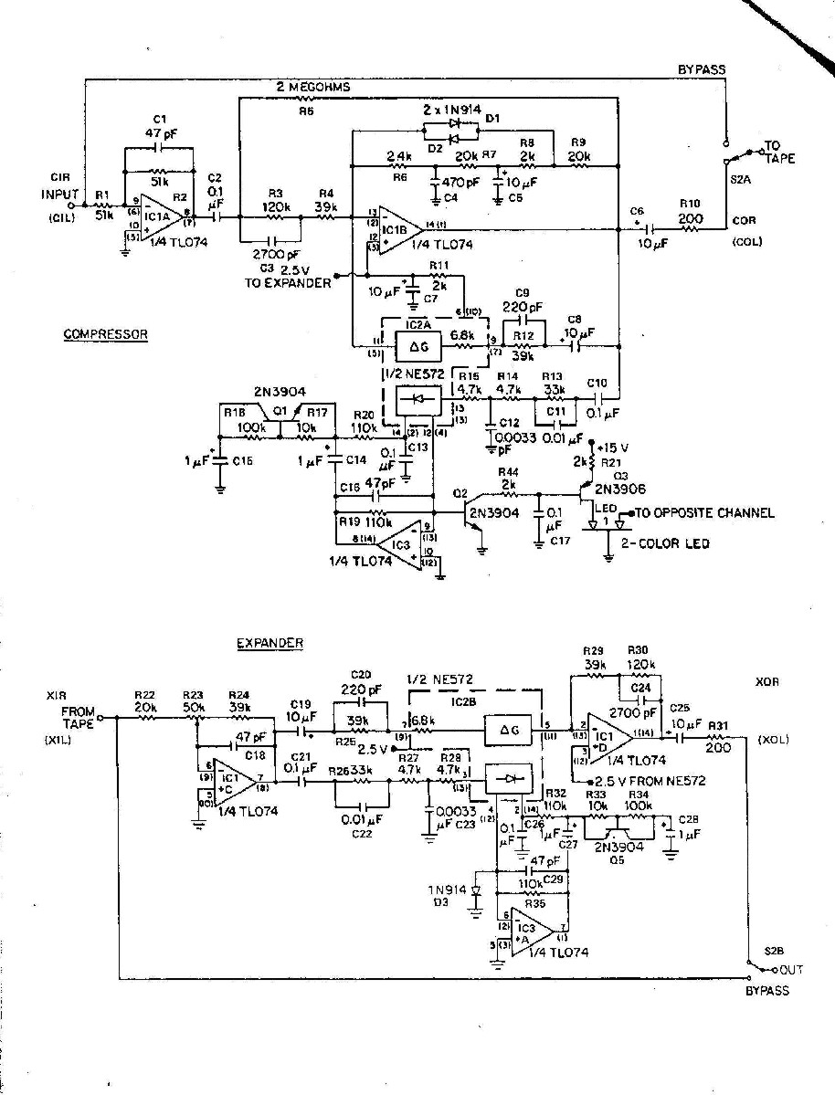
OK here it is, may be a lot to digest,,, it is based around the NE572 that has a fast and slow rectifier output built in (for fast attack and slow release).  Oh course I don't use it that way... I tie the fast attack current port to the virtual earth input of an op amp, to convert the rectified current to a voltage, then use several magic tricks to deliver a long time constant for small changes, a fast time constant for large changes, and added a way to borrow and pay back that fast attack current.  I won't waste your time and mine with any more detail for now, unless there is interest.
I was looking at the old EMT 266 broadcast limiter and they had an all pass network that gave some 300uS of delay. I figured that was what I should shoot for. Douglas Self showed it would take four 4th order filters made up of two 2nd order filters comprising of 2 op amps each. So thats 16 opamps for 291uS of delay down 11% at 20K. I'm sure that would do the trick but its a lot to breadboard to find out, and a lot of resistor measuring:)
The tube compressor isn't doing any better than 0.05% THD anyhow, all those opamps might still sneak under that.
For look ahead the more time the better... IIRC RANE put a look-ahead delay inside a noise gate, so you wouldn't hear it cutting off the leading edge of sounds when the gate opens... they used something like 333 usec which will remove a bunch of the click....

Another very old school trick is to run the recording backwards for non-real time processing... That way the decays are what the compressor sees as attacks and they are all slow rising (easy). The decays are the backwards attacks stopping suddenly which is even easier for dynamics processing.

Sorry to keep throwing odd ideas at you but this is a very old topic. that has been beat around a lot. .

JR
 
bluebird said:
I was looking at the old EMT 266 broadcast limiter and they had an all pass network that gave some 300uS of delay. I figured that was what I should shoot for. Douglas Self showed it would take four 4th order filters made up of two 2nd order filters comprising of 2 op amps each. So thats 16 opamps for 291uS of delay down 11% at 20K.
Sorry I had my math wrong in my previous post. I believe you can do it with only 30 1st-order stages.
2nd-order would take less opamps but component matching would be a headache; with 1st-order all-pass, component values are not critical. I believe the major issue is noise, not distortion.
 
abbey road d enfer said:
2nd-order would take less opamps but component matching would be a headache;
Yes this is already a headache!

JohnRoberts said:
then use several magic tricks to deliver a long time constant for small changes, a fast time constant for large changes, and added a way to borrow and pay back that fast attack current.

Thats what I'm looking for! The NLC circuit in the THAT design notes is not quite doing the trick.

I understand how you circuit is working in general after looking at the NE572 data sheet. The rectifier produces a positive CV for the gain cell so your timing magic is built around that. I suppose I could use the positive CV port on the THAT vca. I would have to build my own fast and slow port. In the NE572 it looks like it has two rectifier circuits, one for each speed. You also have a high pass and low pass filter going into the rectifier, is this to offset the filter in the gain cell loop?

Could you make a quick sketch of how I might implement your timing circuit with the THAT vca? If its too messy don't sweat it.
 
bluebird said:
Yes this is already a headache!

Thats what I'm looking for! The NLC circuit in the THAT design notes is not quite doing the trick.

I understand how you circuit is working in general after looking at the NE572 data sheet.
The 570 series gain cells operate from a control current. The voltage at the smoothing capacitor looks like a resistor in series with a diode junction (an internal current mirror).
The rectifier produces a positive CV for the gain cell so your timing magic is built around that.
The 572 rectifier puts out a full wave rectified current, actually two identical currents, one for the fast attack (small capacitor) and one for the slow release (larger capacitor). I once used the 572 inside a commercial comp/limiter just for the rectifiers. I needed a couple decent rectifiers and that was back in the thru-hole days so real estate in a 1U sku was tight. Two decent, dual output rectifiers inside a single DIP was worth it to me for that application (and I'm cheap).
I suppose I could use the positive CV port on the THAT vca. I would have to build my own fast and slow port. In the NE572 it looks like it has two rectifier circuits, one for each speed. You also have a high pass and low pass filter going into the rectifier, is this to offset the filter in the gain cell loop?
The bandpassed rectifier inputs is a tape NR thing. Since we can't really trust the frequency response of the tape medium between the compression and expansion operation, we narrow up the spectrum we use for rectifier gain setting to reduce tracking errors caused by tape frequency response deviation.  Furthermore we use HF pre-emphasis on compressor input, and symmetrical de-emphasis on expander output to improve HF NR. For the final TMI data you will notice an adaptive HPF on the compressor input using a 0.1uF film cap, and 2M resistor to the inverted compressor output. When the compressor is running at high level unity gain the 2M connected to a -1x output looks like a 1M to ground. For low level when the compressor is running at maybe -10x gain, the 2M looks more like 200k to ground. This is a specialized adaptive HPF filter to remove excessive warp frequency energy primarily at low levels when it is the dominant signal and it can corrupt the signal envelope. This warp energy in the gain control can cause a phantom mistracking during playback because cassete tape won't reproduce much record warp energy. At higher signal levels it delivers the full LF response, or as good as you get from tape. (Sorry I warned it was TMI). 
Could you make a quick sketch of how I might implement your timing circuit with the THAT vca? If its too messy don't sweat it.
I need to think about this... basically the inverting op amp is a variant capacitance multiplier so it looks very slow  for modest signal differences but saturates and becomes fast  above a threshold current... very specific to the 572. 

On the subject of THAT dynamics engines, over on Wayne's forum I gave them a schematic for a variable capacitance multiplier that could be used with the THAT rectifier to make the time constants variable. (I never melted solder but believe it should work.).

Not today but let me chew on this.

JR 
 
Back
Top