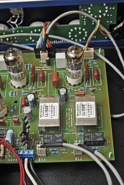
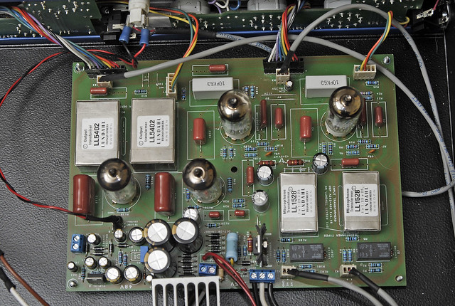
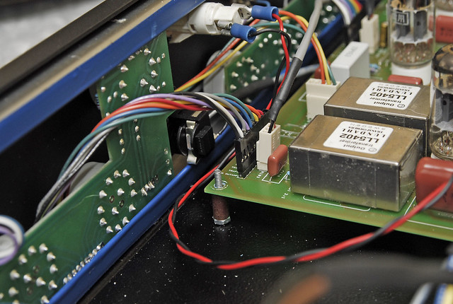
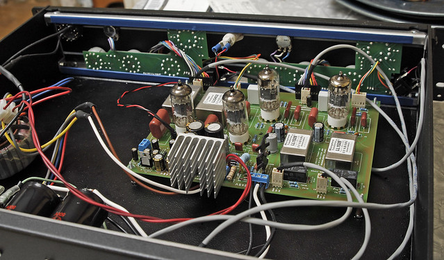
I hope I haven't missed something in the help thread. I have been going through the help thread here for a few days trying to answer my own question, but can't seem to figure it out.
So, ...
1.) Before I go and build an external PSU for my G9 is it possible that I'm getting 60hz him (and it's harmonics) because my C14 and C15 capacitors are undersized?
I'm using 100uf 350V Caps such as these:
http://no.mouser.com/ProductDetail/Nichicon/UPW2V101MRD/?qs=64l3LOSZbCrVK%252bv2Dm%2fH%2fA%3d%3d
1,a.) Should I go to something like these while I'm at it?
http://www.tubedepot.com/cp-jj-100x2-500v.html
2.) Is there some way to tell if I'm getting 60hum from induction, from the 12v PSU, or from the 245V PSU?
I've hot a fluke meter which is telling me that the HT output is 257VDC with about 6mVAC @60 HZ, the 12v output at the panel light is showing 11.89VDC and about 6mVAC. I'm not sure if this much fluctuation is what is causing this hum.
I've done the instrument input mod direct to the PCB with shielded cable and cut the traces, I've tried moving my toroids around in my case and I've shielded them and the power switch from the PCBs, I've grounded the input Pin#1's to the chassis at the same point as the mains ground, and used shilded cable to run from the PCB to the XLR jacks. I'm using the Lundahl transformers.
3.) Where can I find a good description of how to build and hook up the spare PSU board? The layout looks fairly strait forward, but I don't know how to connect the HT caps to it or where to connect the output to the main PCB.
Attached is a screenshot of a scope of the output with nothing connected to the input. When I hook up a mic I get a signal that is amplified and relatively clear except for the 60Hz and its harmonics are overlaid which make it pretty fuzzy. The 60Hz and it's harmonics are present no matter which gain position I use or any other setting and increase (or decrease) along with the output signal as settings are adjusted.
Any help would be greatly appreciated.


![Soldering Iron Kit, 120W LED Digital Advanced Solder Iron Soldering Gun kit, 110V Welding Tools, Smart Temperature Control [356℉-932℉], Extra 5pcs Tips, Auto Sleep, Temp Calibration, Orange](https://m.media-amazon.com/images/I/51sFKu9SdeL._SL500_.jpg)


