The official G9 help thread

GroupDIY Audio Forum

Help Support GroupDIY Audio Forum:

This site may earn a commission from merchant affiliate links, including eBay, Amazon, and others.
You sure?
It feels so illogical. I'm thinking that when the plug breaks the circuit, signal from a guitar/bass etc. wants to travel "to" the PCB??  :eek:
 
The circuit works like this;

Signal comes out from the mic input transformer to the instrument jack. Then comes from the jack to the grid of v1. The signal is then broken by the plug being inserted into the jack.
 
Orphin said:
Nevermind the mod. Right now I need to figure out what's wrong.
I've wired like this:

To --> tip of tele jack
From --> tip of tele jack that breaks when plug is inserted
Ground --> ground

I only get a faint sound from a guitar when I plug it in. It also seems as it doesn't matter if the routing switch is set to line or mic.
However, with a mic inserted to the XLR input the routing switch seems to work as it is supposed to.

I have the same problem, I haven't been bothered to fix it yet, but you'll definitely have to switch to/from over...
 
gemini86 said:
The circuit works like this;

Signal comes out from the mic input transformer to the instrument jack. Then comes from the jack to the grid of v1. The signal is then broken by the plug being inserted into the jack.
That makes sense. Thanks.
 
OK, I've flipped the "to" and "from" and the line in works now, although the routing switch still doesn't make much sense.
With a microphone plugged in the XLR input, the switch cuts when switching to "Line" which seems normal, however with something plugged into "Line", the line in signal seems to be working even if the switch is set to XLR or Line. It also cuts the XLR signal if one is present (quite logically).

It seems like the routing switch is redundant!? (A phantom power ON switch would be enough)

My other preamps works like this and they don't have a switch for XLR-Line. Please explain why it's even there.

Edit:
When trying to figure out the schematic I can only see that the only thing the switch does (when switching to Line) is to change the input impedance for the XLR input.
 
No - you're confusing "line" with "instrument" inputs.

Line input - shares XLR with mic input - attenuates mic input some 30dB and raises input impedance to some 10K, still floating and transformer balanced. Meant to handle line-level balanced stuff.  Also allows for very-high output mics, like U47's in front of bass drums (been there, done that)

Instrument - jack inserted overrides line/mic setting. Unbalanced. Very high-Z (>3M).

Jakob E.
 
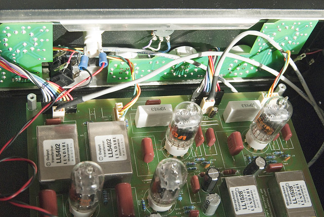
Ok. So I've modified modified the enclosure so that the front panels are no-longer shorting out on the case. Which has fixed the problem that started up when I moved everything to a new enclosure. But the 60Hz hum (and it's harmonics) are still there.

I've checked the 12v and 240V supplies with a scope and they both appear to be pretty clean. (In fact the 240v supply seems a bit cleaner than the 12v supply.)

The volume of the hum seems to be the same independent of the gain or the output settings, but does disappear when I either disconnect the whole 9 pin connector to the front panel on each channel, or when I switch off the power. The hum is equally present in both channels, but when I disconnect the 9pin connector the hum disappears from that channel (along with the rest for the signal). I have tripple checked the pin configuration and have the 9 wires all going from the main PCB to the front PCB in the same order. I haven't tried disconnecting each wire of the 9 pin connectors one at a time, just because it means taking the connector apart. What other kind of things should I be looking for? Would it be possible that I'm shorting something like the ring on the front of the Lorin switches out on the front panel?

Thanks for the help.
-Steve

6932307591_ac635963cc_z.jpg


(more photos: http://www.flickr.com/photos/76511285@N03/sets/72157629294926171/ )
 
If the hum is independent of gain controls, try moving the power  transformers. Also, you'll want to use shielded wire on the instrument jack.
 
Hmm,...
Moving the power transformers doesn't seem to change the hum that I'm getting. I also do have shielded cable on on the instrument jack cables (and the input and output cables). I've had to stop the shield about a half an inch before it is soldered to the jack and the PCB because the terminals are each a bit apart, but aside from that it's shielded.

With a scope it looks like there is no hum when the output connectors are not attached, but the hum appears when I plug the output connectors in to the main board. Does that make sense?

Thanks,
-Steve
 
Sorry, mate. It looked like the wiring for your lamp was the jack wiring at first glance. You might try lighting the output xlr from ground at the connector end. You could be creating a ground loop.
 
Quick question:  what are the HP filter cutoff frequencies of the G9?  I'm guessing they're the same as those in Gyraf's commercial mic pre, ~80hz and 160Hz.  If this is the case, R for a passive first-order RC filter (using .01uF and .022 uF caps) works out to 100k.    How, exactly, is that 100k calculated from the resistors present in the schematic?  I feel like I must be missing something stupid here.
 
I built my second G9 with Edcor XSM2,4k/600 output transformers.

My question is: what transformer termination resistor should i use with them?

I know Lundahl suggest using 10k resistor with LL5402 but Edcor does not provide any such info...
 
sircletus said:
Quick question:  what are the HP filter cutoff frequencies of the G9?  I'm guessing they're the same as those in Gyraf's commercial mic pre, ~80hz and 160Hz.  If this is the case, R for a passive first-order RC filter (using .01uF and .022 uF caps) works out to 100k.    How, exactly, is that 100k calculated from the resistors present in the schematic?  I feel like I must be missing something stupid here.

.01uF into 50K (output trim pot) gives 318Hz
.022 gives 144...

Could pretty much call it 150 and 300, tolerance in both the pot and Cs will push these around a bit...
 
gyraf said:
12V on out ground COULD be one of the 9-pin main-to-front connectors reversed.

Try lifting connectors one at a time until problem goes away, then investigate how 12v gets into that connector.

Jakob E.

Thanks for the advice. I just went through lifting each of the 9 connectors on each channel (the same happens on both channels) and this is the result that I got.

I recorded the audio output too just in case it might be helpful ( http://soundcloud.com/masoste/gyraf-g9-hum )

The recording starts with the unit turned off,
it is turned on and warms up,
the Gain control is increased from the lowest setting to the highest,
Output is cranked from lowest to highest,
Gain is turned back to the lowest setting,
Output is reduced to the lowest setting,
the input, phase and lowcut settings are changed.
Throughout this the hum doesn;t really change much other than the fact that it starts up when the unit is turned on.
Then the connections to the front panel are disconnected and re-connected one at a time in this order:
TO OUTAMP (at this time the hum increases and noise also increases)
TRANSFO- (at this time the hum almost disappears, signal also disappears)
TRANSFO+(at this time the hum almost disappears, signal also disappears)
OUT- (at this time the hum almost disappears, signal also disappears)
OUT+ (at this time the hum almost disappears, signal also disappears)
FROM 48V (no change)
FROM 12V (no change)
then the unit is turned off and cools down.

I also get no change when I remove the LINE or 48V connectors, but didn't bother recording this.

I also tried switching the Out+ and Out- pair with the TRANSFO+ and TRANSFO- pair, but I couldn't perceive a change. (The labeling is different on the main and front PCB, but I though that that was just a labeling error.)

So I'm not really sure what I should be looking for here given these results. Should I still be looking at tracing out the 12V to see if that's getting in to something else on the front panels? It seems like I'm on the right track, but don't know where to go from here.

-Steve
 
Steve,
I suppose you did the Di mod. If so, verify that the switch board gets a proper connection to ground. I attached a picture where to check the connections. Good luck!
 

Attachments

  • G9 connector.JPG
    G9 connector.JPG
    24.5 KB
Thanks for the advice. Yes I did do the DI mod. However, as far as I can tell, it looks like I've got a pretty good ground since my multi meter reads about 0.3Ω from the chassis ground to the jumper that you pointed out and to the ground terminal on the front panel.


The hum does go away immediately if I disconnect the output from the second (290VAC output) power transformer from going to the high voltage PSU. So, I'm still thinking that this has something to do with the high voltage supply.

I don't want to start looking in the wrong location if I'm getting close with to the problem by looking at the front panel and grounding. But, I'm now noticing a slight audible hum from one of my toroidal power transformers now. By this I mean that when I hold my ear down near the transformer I can hear a faint hum. (I'm not sure which one it is and it's pretty faint.) The hum is present weather or not there is any load on the second (290VAC output) power transformer. I'm inclined to try a different transformer here, but these things are kind of expensive. Is there any good ways to test these? Or does any audible hum mean that the transformer is shot?

I'm also looking at this thread and think that maybe I should just go ahead and make an external PSU in order to separate the high voltage PSU from the rest of the board.
( http://www.groupdiy.com/index.php?topic=32559.0 )

Any more suggestions? I appreciate all the help so far.

Thanks,
-Steve


Latest posts

Back
Top