the Poor Man 660 support thread

GroupDIY Audio Forum

Help Support GroupDIY Audio Forum:

This site may earn a commission from merchant affiliate links, including eBay, Amazon, and others.
Kingston said:
radiance said:
Yes, but does that mean you'll have to rethink the attenuator resistance value to still have a sensible range?
Cause there's no way I'm going to redo those Elma's ..

No changes needed.

Thanks Kingston, I'll see if I've something laying around.
My earlier experiement with a Haufe failed royally...
Dunno why it did not work...maybe someone can have a look at the data sheet?? See attached.
 

Attachments

  • HaufeT5223.jpg
    HaufeT5223.jpg
    97.2 KB
seems to be an output trafo, and the frequency response is mediocre. Not all of them happily run reversed as input. The big cinemag 4:1 output certainly did, and sounded great, but that doesn't mean anything here. Also that 300kohm looks strangely high impedance for a trafo.
 
A transformer reflect impedance... If you put a 1:1 ratio transformer in front of the input attenuator you'll have a reflected impedance of about 10k.
There's a chance that changing the input transformer will improve the distortion ratio but it won't solve the major problem :
In a push-pull design most of the distortion comes from the misbalance between the push part and pull part... So the two parts of the design must be perfectly balanced to acheive a null into distortion. The balance must be perfect between the input and output transfos, and between the gain curves of the tube push-pull. If one of those part fail in matching, the distortion will rise and thump will be audible.
As I always said, try to match your tubes before changing transformers. The main problem is there.
 
king-rb said:
hi all together. i rewired my poorman to make the error tracking easyer. now its working and i like what it does but there are problems with the frequency response. what can cause such a bad frequency response?
also what can cause this distortions in the signal?

I don't understand what are the two traces on the graph but the freq response doesn't look bad on the upper one (-3db at 20Hz is really correct for a transformer based design ). The second trace is weird with those peaks and dips : I noticed that they are 50Hz harmonics... You live in Germany and the PSU runs on 50hz based current. I'd bet the audio transfos are catching the PSU transfo magnetic field or the filament PSU is regulated and regulators don't have enough power to do their job...

General information about transformers: be carefull, most of the data sheets are giving the distortion @ 50Hz. At lower frequencies, distortion will be worse and gain will be most of the time lower...
 
ANOTHER ONE BORN!!!

Sorry for screaming.

Just finished (almost) one Poorman. No problems at all, it was running smoothly from the first startup.

I used Edcor Powertrafo with extra toroid for heater. 6n5p tubes. etc.

The only little weird thing is the treshold, it it starts to affect ony after half way up and then suddenly really hard...hmm?!?!?!?

The other one is that my heater voltage is now 5v. Is it ok?

Time constant is not ready yet, going to use bluebird values, stock one has too slow attack for my taste.

EDIT: actually, there's more problems: severe lack of low end....any ideas where to start looking?


OK, solved. It was a combination of many things: bypass boards, wiring etc.

Sounds VERY good indeed already without any time constant mods. I have Edcors in & out and I find the critisism towards them rather unfair.  Ok, Lundahls sound more transparent but I liked my LA2a with Edcors so I thought I should try them here too, althouh it is completely different type of circuit.

To get this thing sound good with Edcors you need to take care of the symmetry of the signal. To match the tubes well and to find a nice pair of Edcors for input and signal amp out.

Thanks Volker & Analag!
 
Ok, done!

We matched the 6n5p's and it now sounds sweet!!!

The only problem was that we didnt have 4 identical 5687's, so it resulted in weird readings on VU and overall unbalance in stereo link mode. After we used the two Tung-Sols and GE's in both channels it started to work perfectly.

The TC circuit is as follows: (in parallel)

25k/1.2uF
68k/1.5uF
150k/4.7uF
470k/6.8uF
none/10uF
10k/10uF (in series)

I was able to keep the C4 in place by using the attack connector like Tekno808 suggested. (page 143)

Heater voltage is now 6.1v by using 0.68 (25W) and 2.2k (10W) in parallel. The powertrafo for the heater is the Edcor 9v in parallel with 2x9v 50VA toroid, with both primaries in 110v and then in series to achieve the 230v pri.

I used the hairball 8020 VU with 5k trimmer, works like charm.

It is absolutely one of the nicest sounding vari-mu's i've ever heard.
 
I've used the RCA Ba6a a lot. And Altec 438c. Manley has been in few session. I remember trying Knif Vari but don't really remember anything about it, so i wont compare. And few others that i cant remember now. But i've never tried the original 670, except as plug in  :-[

 
I've always felt that the PM 670 produces much heat. I always wondered where the heat really is. I did some measurements using a cheapo laser thermometer.
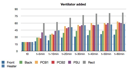
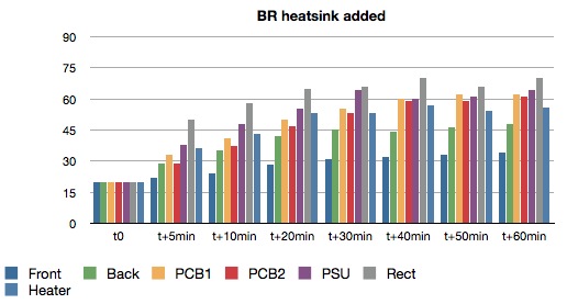
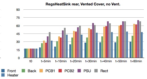
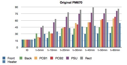
I've measured the temperature at the front panel, back panel, above PCB one and two, above the PSU, close to the bridge rectifier and above my slow start heater PCBs. I did not measure the slow start heater regs themselves. I measured at power on (t0), t+5,10, 20, 30, 40, 50 and 60 minutes. I've closed the lid between measurements. Since the accuracy of laser thermometer is distance dependent, don't expect very precise results here, but it gives a good impression.
My first assumption was that the most heat would be close to the tubes, but that was wrong. The highest temperatures were above the PSU and close to the rectifier.The bridge rectifier was mounted directly on the side panel of my steel enclosure, the slow start heater regs are mounted directly to the rear steel panel.
Since I live in a metric world all temperatures are in °C.

3.jpg


As you can see, the PSU went up to 81°C (or, more precisely, the air above the center of the PCB), the rectifier's max. was
89°C.

Then I've put a small 12V ventilator, powered by 8,3V coming directly from the bridge rectifier, at the side of the PSU. The improvement was huge, but not for the BR, quel surprise:

1.jpg


Then I've mounted the bridge rectifier to a heat sink. Much better:

2.jpg


Conclusion: the addition of a small fan and the proper use of heat sinks gave me a big improvement.
Less thermal stress for the components. I personally think that it is not necessary to mount the tubes off PCB.
Some 48°C overall temperature is OK for a tube device, me thinks.

Edit May 23th:

Here is a passive version. I removed the fan and mounted the slow start heater regs on heat sinks outside the enclosure.
I also used the vented cover as suggested by Kingston.
(http://www.modushop.biz/ecommerce/cat098_l2.php?n=1)

4.jpg


Very interesting Holger!

What I've found in my unit is that the slow start heater regulators produce by far the most heat, closely followed by the heater rectifiers (one for each slow start heater board BTW).
All  for regulators from my PSU are mounted on one big (huge) heat sink which get barely too hot to tough...say, I can tough it for 1 sec. but not longer.
 
My unit is also quite littered with big heat sinks, flowering out the back panel in fact. Early on in the thread it was suggested to use vented covers (http://www.modushop.biz/ecommerce/cat098_l2.php?n=1) and at least a single empty space above the unit. That's a minimum requirement.

You can go passive, just need more physical space and aluminum.

I've calculated the single biggest source of heat in my unit are the 5687 tubes. More than 25 watts of pure heat from the heaters alone (stereo unit). That sidechain is one inefficient and stupid brute force beast. Like installing an oven in your otherwise perfectly healthy compressor.
 
Holger said:
The brute force side chain can also be found in the Fairchild, right?

brute force yes, but not quite this inefficient. 5687 is a kind of weak tube for this task pumping the timing caps, and just generates an awful lot of heat.
 
Inefficiency is how poor men do things; live in crappy old houses for low rent and pay a premium for heating and cooling the leaky old beasts.  Go to laundromats, etc. 
 
Back
Top