the Poor Man 660 support thread

GroupDIY Audio Forum

Help Support GroupDIY Audio Forum:

This site may earn a commission from merchant affiliate links, including eBay, Amazon, and others.
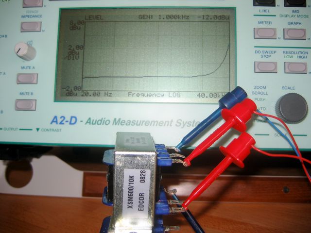
There seems to be a trend of this sort of roll-off in builds now and then, mainly LA-2A builds. Can't say I've noticed anyone trying another Edcor in the search for a fix.

Quality control: everyone should probably take the time to test all of their Edcors before using in any project. There are enough reports of mis-wired and open connections as shipped to warrant user scrutiny. Same would surely hold true for other issues. I know I couldn't wind transformers at that price and hope to offer real QC; only good customer service for problems as received. Edcor has been great about shipping out replacements in problem cases I've had. Not a 'thumbs down' comment at all, just a reality check on the real value of $10.

Maybe altogether unrelated to your problem; could be your card doesn't have enough drive for the load, but I doubt that.

Was I going to say something about filament supply earlier? No, I already said it. :razz:
 
[quote author="Kingston"][quote author="Moby"]regulated heater supply (what I prefer because saving tubes life)[/quote]

Tube doesn't care if it's getting filament voltage somewhere in the ballpark, so a perfect 6.3V regulation won't make your tubes last any longer.

Some say heater voltages affect sound, but I personally think the design is broken if it can't handle slight deviations. Remember fairchild was designed at the time when 10-20% or something equally ridiculous was the normal deviation for all parts so that was taken care of in the circuit. AFAIK any good tube design still does this, including the poorman.[/quote]

Just to back up Kingston...
I built a 1-Bottle Pre & the filaments were running a little over = about 6.5 - 6.7. Something didn't sound right & I also could he a slight crackling or fizzing sound, so I added a 1ohm resister to the heaters & it dropped to about 6v (or so) & the crackling & fizzing sound went away & the pre sounded a lot better... not just because of the (now gone) extra noises.

Keep in mind this was a "Mic Pre", not a line level unit like the PM670, so it MAY have been more sensitive to it but thought I'd share.

This was my first experience with hearing how the heater voltages can effect the sound & performance.
 
i've got a pair of huge Freed's that could do the job - but only a pair won't save me.....
 
Huh, that Edcor issue can be a real problem. I'm still waiting for my transformers and it will be nice to know is that "issue" or something else. It will be great if someone can measure Edcors, but with proper termination. It's great to know that Edcor will accept transformers back but sending them and accepting back will cost . I don't want to judge before we know the facts but I will be dashed if Edcor has no validation process :cool:
Tube doesn't care if it's getting filament voltage somewhere in the ballpark, so a perfect 6.3V regulation won't make your tubes last any longer.
Sorry, but I have to disagree. Slow turn-on and stable voltage save the filament life and that's a fact. I just share experience of the people older than Tubes we use :wink:
 
It will be great if someone can measure Edcors, but with proper termination.

- on the 600R side i dont think you need any termination - just as in real life where you would insert or patch the comp directly from a line out.
- on the 10K side i think you need to "emulate" the circuit's load - 30K?...dont know..
 
Google can help but here's the one link . Not a big deal with termination but transformers like to see some termination for proper frequency response. :wink:
http://www.shine7.com/audio/LL1545a.htm
 
Here is a picture of measuring a (naked) Edcor 600/10K
[Z out 15 Ohm, Z in 100K Ohm]:

IMG_5212.jpg
 
A question, where is a good place to get the 12 volts for the bypass relays?
Is that what the tap next to the +/- 17volts output is for? Can I use this and drop the voltage with a resistor?

Thanks
David
 
Anyone who is using the Elma switches:

any tricks for soldering the resistors on Position 0 and position 12? The solder tab is right behind the screw holding the switch together.

also position 23 is zero value... right?

Building an attenuator is something I have never done before.

:?: picture will tell me everything if you got one :!:
 
[quote author="dspruill"]where is a good place to get the 12 volts for the bypass relays? Is that what the tap next to the +/- 17volts output is for? Can I use this and drop the voltage with a resistor?[/quote]
use the trimpot RV1 to adjust the +17volts to +12V

[quote author="cannikin"]any tricks for soldering the resistors on Position 0 and position 12? The solder tab is right behind the screw holding the switch together[/quote]
have a look at the wiring guide to get an idea.
can post a photo of mine tonight.
 
Hey Guys,

I started building my Poorman and had hit a snag... the BOM states the resistors for the most part are 1/2 Watt's... problem is I can't find any half watt's that fit the board footprint (we are kind of limited to what we can get here in Africa) it seems the board size is for what I can get here are 1/4W's, the half watters are double the size and don't fit the board.

I'm sure that the 1/2 Watt's were chosen for a reason, so I'm guessing 1/4W's are a no go?

And if they are not, anyone know if RS has what is needed or anyone willing to order me the resistors and I'll cover your costs?

Much appreciated!

Matt
 
[quote author="Gachet"]Hi,

Is that needed to provide mica isolation between hi voltage regulators and heatsinks ?

Thanks[/quote]

Um, unless the heatsinks touch EACH other or the chassis, then no isolaters are not needed. The idea of using the isolator is to make sure it doesn't short... if the reg is not touching anything i.e via touching heatsinks or chassis, it can't short :thumb:

Cheers

Matt
 
Matt,
I used 1/4W resistors in my Poor Man without any problems.
(the footprint is a standard 0207, the 1/2Ws I have fit in there nicely?)

Gachet, yes, please mount the regulators isolated to the heatsinks.
not for elcetrical (the heatsinks are not grounded or connected to anything), but for safety reasons.
it is too dangerous to touch the heatsinks accidently
 
[quote author="cannikin"]Anyone who is using the Elma switches:
any tricks for soldering the resistors on Position 0 and position 12? The solder tab is right behind the screw holding the switch together.
also position 23 is zero value... right?

:?: picture will tell me everything if you got one :!:[/quote]

elma.jpg

these are stopped to 21 positions
for the inner deck just unscrew the outer one
 
[quote author="[silent:arts]"]Matt,
I used 1/4W resistors in my Poor Man without any problems.
(the footprint is a standard 0207, the 1/2Ws I have fit in there nicely?)

Gachet, yes, please mount the regulators isolated to the heatsinks.
not for elcetrical (the heatsinks are not grounded or connected to anything), but for safety reasons.
it is too dangerous to touch the heatsinks accidently[/quote]


Thanks Volker,

Yeah it seems my local shops don't have METAL FILM in 1/4W, and what they said were 1/2W's are in fact 1W... go figure.... good to know that the 1/4W's are working out. I'll prob go in that direction unless I can find 1/2W's easily.

RE the isolators... safety who cares about safety!!! :shock:

As I shared, as long as the heatsinks DON'T touch you are fine... but if they touch YOU... well lets just say it won't be pretty... for the cost of a few cents the safety is worth it...

Cheers

Matt
 

Latest posts

Back
Top