the Poor Man 660 support thread

GroupDIY Audio Forum

Help Support GroupDIY Audio Forum:

This site may earn a commission from merchant affiliate links, including eBay, Amazon, and others.
Moby said:
I will remove ALL my posts & voltage chart & I'll look elsewhere for help if that would make everyone happy.
No,no, that will be the waste of energy! i think that we are here to help and understand each other. I don't have a problem because you are posting a lot, I'm sorry because I can't give you voltage chart .Mine PM's are half finished and it worked once (out of box) but I decided to finish it, so now its in a parts again....  :-\


Guys, be more positive and don't give sucha harsh comments.

Thanks Moby... I will be more careful how & what I post & I appreciate your understanding.
Eventually we'll get more voltage charts which will be helpful to all.

I took a break tonight ...had a gig with my band & a few drinks.  :D
Maybe this week when I get some new Tube sockets I'll have better luck.
 
wtmnmf said:
$.02:  Put a quick summary on a post-it, stick it on and lock it in the closet for a few weeks.  Engage your energy in something fun and productive.  Don't even think about logging on here.  Listen to some music that you like :)  This sh!t is not important.  Come back to it when you think it will be fun again.  When you solve the mystery in the right frame of mind you will enjoy it so much more and you can share that success here. Everyone will think your a wizard if it was complicated or have a good laugh if it was a stupid error.  Either way it'll be fun and entertaining.

Best of luck to you.

I found that thinking of troubleshooting while doing something else (and not beeing near to the faulty unit) really helps. It makes you consider ALL possible options on where the fault could be AND you'll get to see the big picture.


Oh, and that's a very nice unit you've got there Eddie!!!

 
SaMpLeGoD said:
Hello, just post to put a really bad quality photo of my PM670 and my quad SSL9K...
One channel of my PM670 still is not working properly... but here it goes to you...

Nice work!  ;D

Cheers,
--
Don
 
Im gonna repost in the hope that I might get some help on this expensive paperweight...Please

Ive put the beast aside for a couple of weeks now hoping to clear my brain.  Its fully built but after a big spark somewhere in the psu, probably related to my non-isolated regulators, I lost the two high voltage rails on the output of the PSU.  I do have good voltages coming out of the transformer.  I think something like 260 Volts and 150 Volts.  I'm not sure where to begin with the tracing.  Another problem is that my schemes have disappeared somewhere along the line.  I have things isolated and replaced both regulators now.  I checked with my continuity checker all of the diodes in the path and they seem to be working correctley.  Can someone post some key places I can test along the high voltage rails to see where the problem lies.  After the big spark incident Im a bit wary of sticking anything in that case.

For more info on my dilemna check here
http://www.groupdiy.com/index.php?topic=28274.msg413283#msg413283

Thanks

Will
 
Lost 'private' schematics are a real problem for you, no doubt.  How can Will get a replacement?  I'd figure where you do and don't have voltages, for starters. 
 
Eddie your pics look fine & the units look GREAT!  ;D
Nice job.  I really like my SSL9k Pre-amps.

This sh!t is not important.

I actually disagree, it's very important to me. I can't even begin to list all the equipment I've built that gets used in my studio every day.
Also, without the "Technical Knowledge" to repair all the equipment I own, I'd be broke by now... paying someone else to do it (IF I could find a good tech in my area that was good & cared about what he was doing) I've been thru that nightmare.

On a positive note:
I don't think I've talked about the "sound" of the PM670 enough...
From what I've heard, doing some testing on Vocals, Bass, Guitar, etc... This thing sounds really cool!
I have NOTHING in my studio that compresses like it does... this is why I'm so excited to get working properly.
I'm mixing 2 album projects starting in about 2 weeks & would LOVE to have the PM670 up & running for mixing.

A good friend of mine that helps me in the studio a lot & knows what he's listening to, was shocked at what the PM670 did to his guitar track on a particular song. We needed to compress this track & it never sounded right with any other comp I have (& I have a lot) It needed control. All my other comps robbed it somehow... but the PM670 controlled & enhanced it.

I should mention that I have a switch on my unit that allows me to choose the stock 10uf or a 2uf with a 68k, 180k or 470k parallel to it... the 2uf with any of the resistors were our favorite. The 10uf had too slow a release for my liking.
 
W DeMarco said:
Im gonna repost in the hope that I might get some help on this expensive paperweight...Please

I do have good voltages coming out of the transformer.  I think something like 260 Volts and 150 Volts.

Will

expensive paperweight... I'm trying to save mine from that as well.

About your voltages - 150v ? This doesn't seem right... where are you measuring 150v AC?
& which Transformer are you using?

You should have:
15-0-15
250-0-250
9v (heater)
 
emrr said:
Lost 'private' schematics are a real problem for you, no doubt.  How can Will get a replacement?  I'd figure where you do and don't have voltages, for starters. 
with all respect the 'private' discussion gets boring and has been discussed to eternity.
up to now everybody's schematic got a replacement if needed, even some PCBs.
Will gets some replacement too.

khstudio said:
...On a positive note:
I don't think I've talked about the "sound" of the PM670 enough...
From what I've heard, doing some testing on Vocals, Bass, Guitar, etc... This thing sounds really cool!
I have NOTHING in my studio that compresses like it does... this is why I'm so excited to get working properly.
I'm mixing 2 album projects starting in about 2 weeks & would LOVE to have the PM670 up & running for mixing.

A good friend of mine that helps me in the studio a lot & knows what he's listening to, was shocked at what the PM670 did to his guitar track on a particular song. We needed to compress this track & it never sounded right with any other comp I have (& I have a lot) It needed control. All my other comps robbed it somehow... but the PM670 controlled & enhanced it.

I should mention that I have a switch on my unit that allows me to choose the stock 10uf or a 2uf with a 68k, 180k or 470k parallel to it... the 2uf with any of the resistors were our favorite. The 10uf had too slow a release for my liking.

and I had the impression / bad feeling your unit doesn't work. ;D
modifications are not supported. if you like them it is fine.
 
[silent:arts] said:
and I had the impression / bad feeling your unit doesn't work. ;D
modifications are not supported. if you like them it is fine.

Don't get me wrong... I still have issues & this test was only using ONE channel (the one that seems to measure well) BUT my PT is still overheating... even with just this one channel. So I still have some work to do.

I just thought I'd post something positive & explain my excitement.  ;D
 
Somebody buy Volker a beer  ;D  Grab me one while you're at it.  ;)

One suspicion is that Kevin's threshold is already too much drive at position one (390 ohms to ground, out of 15K total, I recall).  The positions arrived at via many of the calculators are meaningless without doing a log step to dB comparison.  I've suggested experiments with a different taper, as he's seeing a 50% reduction of signal test voltage at that position.    Anyone having that problem can simply parallel another set of resistances to ground across that 390, or whatever, and find a better starting point for your taper, before you trash and rebuild it.  I wouldn't want to rebuild that switch, which is why it would be helpful for anyone with any real world experience to comment further on their action.  Anyway, Kevin may be listening to far more compression than he realizes.  I think he can't get it past that point on the threshold without distortion.  I've not noticed mention of the SC amp gain, which could inform any decisions regarding threshold taper.  It's a simple measurement someone with a working unit should take, along with some observation about signal threshold (test signal of 'x' dBm at grids of V3/4 is onset of compression in audio amp). 

Kevin's power trans and PSU Q4 heating are of real concern, and his swimming cathode voltages don't make any sense to me.

Here's a DIY thought for anyone hopelessly confounded by their PM.  This is a damn simple circuit.  Simple enough to consider the purchase price as applying to the schematic and power supply board, with free audio amp board thrown in.  So, start over and build the audio amp by hand, on something else.  See if that one works.  Compare it to the one you built on the provided circuit board; it may help you fix or understand that first failure. 


Volker,
I spent a lot of time making a Voltage chart for this project.

Could you PLEASE post a link to it (& that page) on your 1st post?

Also... if you don't mind, I think it may be taken more seriously if you asked others if they could fill out the chart.

It would really help out ALL builders.

Once again... I apologize if I seem pushy... I'm just the type of person that doesn't like to give up & if you could see this unit & how "Random" the voltages & problems are you'd understand... I'm starting to think the tube sockets may be faulty or just plain crap.

Thank you.  ;D
 
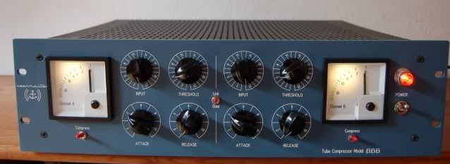
Yesterday I finished my version of the PM670:

front.jpg


The frontpanel was first painted and then engraved. Case is modushop, knobs by Banzai.
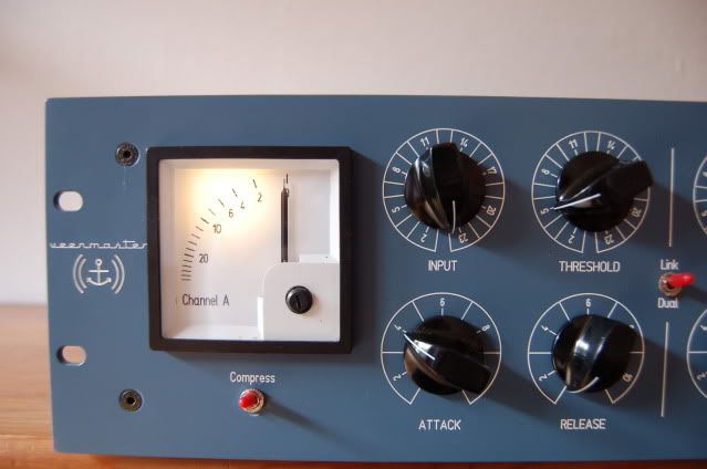
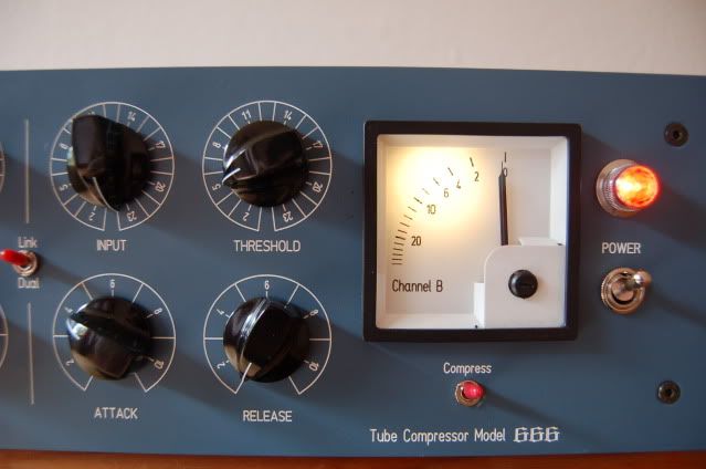
The meters were a bit tricky: I tried Sifam AL22 which I had laying around here, but somehow they didn´t work. After lots of trying I ended up with these 15V DC meters and a custom made scale. I changed R6 for a 5K trimmer and adjusted it for a 15 V voltage drop for full scale reading. One problem though: when both channels compress the same amount that voltage drop is different between both channels, so the meters show different values. ??? Anybody knows a solution?
In the end it´s just a cosmetical thing and this beauty works great so far.
I would like to thank Analag, Volker, Lolo and Rotheu for making this project possible to us and of course the rest of this wonderful community. I´m really happy I found this place of endless inspiration and knowledge.
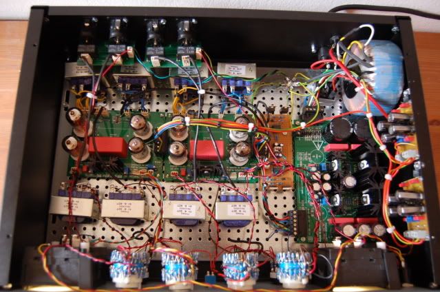
Some more pics:

A.jpg
B.jpg

inside.jpg


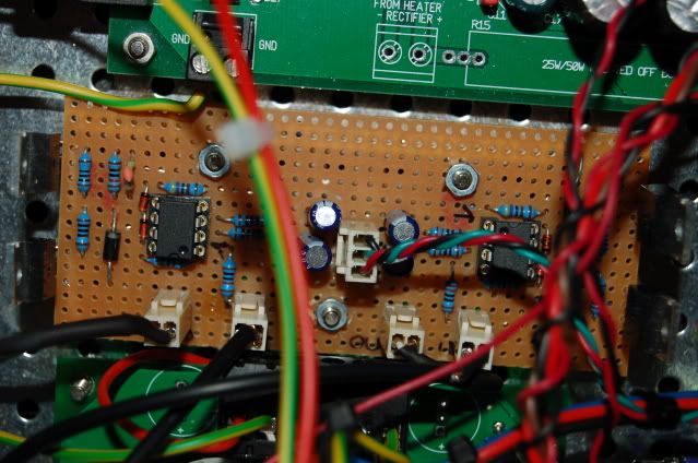
SCAMP by Lolo on Veroboard:
scamp.jpg


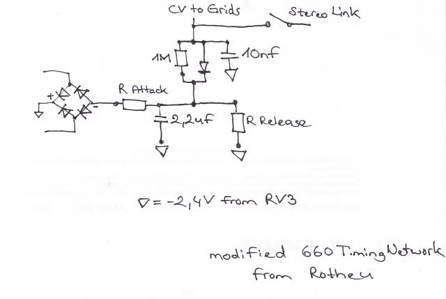
I chose a Timing Network inspired by Rotheu:
TCnetwork.jpg


I use 11 positions each for Attack and Release.
These are my chosen R Values for Attack:
43R
130R
330R
470R
1,3K
2,2K
3,16K
4,7K
9,1K
13K
18K

My R Values for Release:
18K
22K
27K
33K
39K
51K
62K
82K
100K
130K
180K

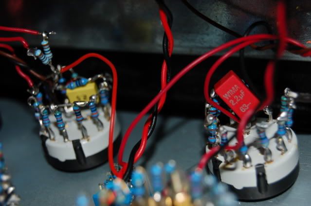
Switches (Attack with red, Release with yellow Cap):
attack.jpg


Regards, Emre
 
You know your right Kevin.  I havent been in there for a while so Ill remeasure to make sure.  I was thinkin about the output of the psu and its multivoltages!

Volker,  Ive been a real pain in the arse, first the slowstart stuff now I lose a schemie.  Sorry but I do appreciate your help and this project.

Will
 
veermaster said:
SCAMP by Lolo on Veroboard:
scamp.jpg


I chose a Timing Network inspired by Rotheu:
TCnetwork.jpg


I use 11 positions each for Attack and Release.
These are my chosen R Values for Attack:
43R
130R
330R
470R
1,3K
2,2K
3,16K
4,7K
9,1K
13K
18K

My R Values for Release:
18K
22K
27K
33K
39K
51K
62K
82K
100K
130K
180K

Switches (Attack with red, Release with yellow Cap):
attack.jpg


Regards, Emre

I know this thing  :D :D :D !

Out topic little question : Isn't your slower attack setting dividing the maximum gain reduction by 2 ?

BTW, nice design !!! Here is the first SCAB mod released... I should take some time to finish my unit  :-[...
 
Why do people line up the transformers in their builds?.
 
  Look at guitar amps etc often the transformers are at 90 degrees to each other to minimize the coupling.
 

Latest posts

Back
Top