the Poor Man 660 support thread

GroupDIY Audio Forum

Help Support GroupDIY Audio Forum:

This site may earn a commission from merchant affiliate links, including eBay, Amazon, and others.
Chuck, we have two transformers of identical ratios that counteract one another's gain.  Unity+1 tube stage.  Or, gain/gain/loss.  Measure the level of a test tone at each point, and it should tell you something. 

You haven't damaged your tubes.  I'm 99% certain.


Thanks for the reply Doug.

When you say gain/gain/loss I am assuming you only mean the gain amp portion of the design.
For mine I see a Loss/Gain/Loss across the [600/10k] [Tube] [10k/600] 

So I guess the problem is that first transformer?
I should see a gain when I see a big loss, is that correct?


Chuck
 
correct, just the audio amp.  transformer (gain) / tube (gain) / transformer (loss).  Is your 1st transformer backwards?
 
Well I was almost offended at the suggestion that I could have wired up my transformers backwards but decided to try some Edcors I have the same just to see if the transformers were all shorted or screwed up...

And you will never believe what I discovered, In part Doug you were right!
But it wasn't me that wired them up backwards but Edcor labeled the tops backwards. When I flipped them over all 4 transformers were exactly opposite.

Here are some photos just for fun.

edcor_what1.jpg

edcor_what2.jpg

edcor_what3.jpg

edcor_what4.jpg


Thanks Doug!
I live to fight another day

Now I have to put it back together and see if it works....

-Chuck
 
Kingston said:
This illu. is only for on deck, Am I right?

Kingston said:
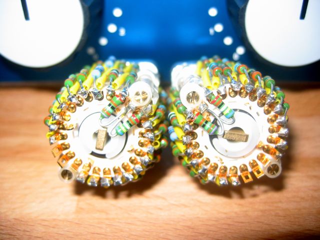
A little logic puzzle. Start from step one with the switch. How do you make Rx = 13809 ohms (deck 1), Ry = 1191 ohms (deck2)?
Hmm. Maybe I can't figure this out either but I would say step 2.

Step 1, Attenuation = 23 dB, Rx = 13938 ohms, Ry = 1062 ohms, Resistor = 1062 ohms.
Step 2, Attenuation = 22 dB, Rx = 13809 ohms, Ry = 1191 ohms, Resistor = 129 ohms.
Step 3, Attenuation = 21 dB, Rx = 13663 ohms, Ry = 1337 ohms, Resistor = 146 ohms.
As I can see I have to place the first resistor 1062 ohm on the common terminal and the next 129 ohm from pin 1 to 2?

Cheers
Soren
 
Remember, this is a tapped attenuator. We stop caring about attenuation levels below, say 24dB. It means we never go through the full ranges of 15kohms of either deck between the wipers (grids) and transformer.

BUT

We still always have the full 15kohm ranges between transformer and control voltage.

Draw it on paper before soldering anything.

It is quite the puzzle and I wouldn't be surprised if a lot of the tube mismatch etc. gain problems seen on this thread have something to do with mis-wired tapped attenuators. The wiring guide for example, shows a full range attenuator (with deck 2 reversed! careful there!), and is not compatible with the charts I have posted.
 
Kingston said:
...
It is quite the puzzle and I wouldn't be surprised if a lot of the tube mismatch etc. gain problems seen on this thread have something to do with mis-wired tapped attenuators. The wiring guide for example, shows a full range attenuator (with deck 2 reversed! careful there!), and is not compatible with the charts I have posted.
it is not too hard if you think of it as a potentiometer.
and it is a good idea to match the resistors for both decks.

where is deck 2 reversed in the wiring guide ???
I just rechecked and can't find a mistake ...
 
[silent:arts] said:
where is deck 2 reversed in the wiring guide ???
I just rechecked and can't find a mistake ...

OK not necessarily a mistake, but just a thing to keep in mind. Especially for tapped attenuator, both decks should be soldered so that the resistor banks are equal, both decks having same resistor values at same positions. That means deck two end point wires will be reversed compared to the guide.

Create two opposite direction resistor banks (like the guide assumes), and trouble shooting will become a real bitch for tapped attenuators.

The main point still is that the wiring guide ONLY works for full range attenuators, which is not what I believe most people are using.
 
but you noticed the little numbers in the schematic ...
the "decks" are drawn reversed there (symmetrical design).
thus: both decks at the switch are exactly the same, with exactly the same resistor values at the same positions.

Create two opposite direction resistor banks (like the guide assumes), and trouble shooting will become a real bitch for tapped attenuators.
mhm, I can't see this assumption.

The main point still is that the wiring guide ONLY works for full range attenuators, which is not what I believe most people are using
nope ;) I find it useful to have an "off" position.
with a higher resistance between step 1 & 2 you can make pos1 "off" (no audio), and have 1dB steps for the other positions.
you can make the steps to your taste ...
if you don't want the off position solder the desired additional resistors between step1 and the PCB PL1/2.
 
[silent:arts] said:
but you noticed the little numbers in the schematic ...
the "decks" are drawn reversed there (symmetrical design).
thus: both decks at the switch are exactly the same, with exactly the same resistor values at the same positions.

Thanks for clearing this, and sorry for possibly confusing others.

As for the rest, we're just talking preferences.
 
Thanks for the answers both of you. Now I just have to chew on them. After some drawings I began to see some consistence.
Sorry for the newbie question but I can see that I don't fully understand the potentiometer topology.

Where should I put this resistor?
Step 1, Attenuation = 23 dB, Rx = 13938 ohms, Ry = 1062 ohms, Resistor = 1062 ohms.


Cheers
Soren
 
I'm wondering about my B+ voltages. They are 246.5VDC and 131.6VDC, and very stable. From building other stuff I know 5687 is fine even with even +-10VDC, but just how fussy are the 6BC8 tubes over their B+ voltages?

should I tweak it up to 136VDC?

Currently I'm seeing more cross-over distortion on high compression than I'd like even with matched tubes (much like bluebird earlier in this thread), and I'm wondering if (and how) B+ has any effect on that.
 
Still fighting with cross over distortion. Very prominent with modern mix levels. I realised the amount of compression has no effect on it.

Other things,

This is the first unit where I can really hear the edcor XSM 600/10k step up transformer at work. I can't say I like it much. I was surprised how grainy it sounded and how it ***** all over "s" frequencies. No good. I'll start looking for alternatives. Lundahl certainly has a few that fit my mid-side plan.

I've used the 10k/600 step down in many topologies already (as output of course) and it always works and sounds good, so I didn't expect the step up have a more pronounced effect. Probably output transformers are the better place to "color" stuff, and input should be something much more transparent.
 
Hmm, I doubt it's the input transformer adding s-**** color.  I'd be surprised if you were anywhere near saturating it.  What makes you think it is the contributor?  An input on a tube preamp is a much greater step, and they're never a problem. 
 
sorry edited the above post while you had already typed yours.

anyway, I did not mean the transformer is saturating. I know it isn't, since it's rated for a ridiculous 2.5 watt level. I just meant its performance in general is less than stellar. I'm used to lundahls and cinemags and they sound much better in the high frequency areas. That comment was unrelated to the cross over distortion I'm seeing.

The crossover distortion happens even if I don't compress at all now that I've tested further. Put high enough level through the 6BC8 amp and it's there. It's there on moderate levels as well actually, just not as easy to detect (with my hack of a scope anyway).
 
This is the first unit where I can really hear the edcor XSM 600/10k step up transformer at work. I can't say I like it much. I was surprised how grainy it sounded and how it ***** all over "s" frequencies. No good. I'll start looking for alternatives. Lundahl certainly has a few that fit my mid-side plan.
Yes, EDCORS are really poormans transformers  :( "****" in the high frequency is caused by huge nonlinearities in the 60k region. Firstthing I did when I recieved them was measuring and I was really dissapointed, but they are OK for prototyping  ;). Lundahl are really transparent and no way it's comparable to the EDCORS. If you want clean sound that's the way to go. If you ask me I will go with Jensen.
Regardind crossover distortion it's probably caused  by EDCORStoo because they are not symetrical (try to measure the Inductance). In the puh-pull arrangement it's really important. Of course I read that you matched the tubes. Hope you did that with various grid voltages  ;)
BTW, do you have hum problem?
 
I had a hum problem... got rid of it by working on placement the Power transformer, and the rectifier. Plus placing a ton of metal shielding in front of it. Spend a lot of time with this. I also removed the slowstart PCBs. generally thicker wires...and The wires going to the meters, should also be placed away from the audiopath, and be shielded.  My unit is now quiet as a sleeping lamb! Sounds fantastic, and tightens the bottom end in a terrific way. luve it! 

But YES,  I have the same distortion problem as mentioned...! I also hear it in the lower frequenzies.  And I can't use it on nicer clear recorded material.. My gutz feeling is that it is caused by the edcores. If a possible replacement alternative comes up, I'm all over it.


Latest posts

Back
Top