sahib
Well-known member
Update on our Total Audio Control 500 system. Now 6, 3 and 1 slot desktop versions added.
All versions are GDIY 51X, API and Radial compatible.
11 SLOT

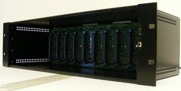
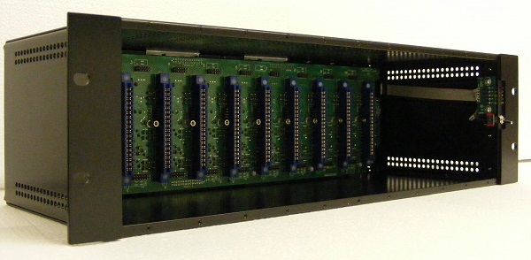
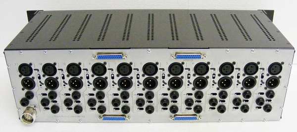
6 SLOT
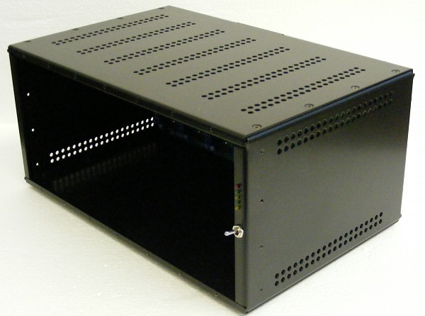

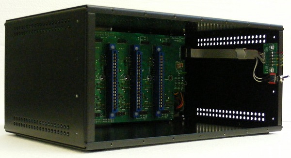

6 SLOT WITH RACK MOUNTING BRACKETS
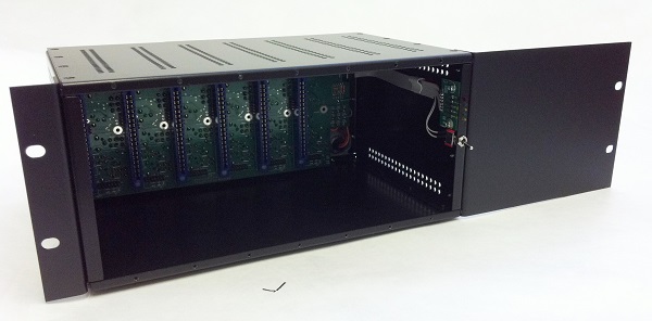

3 SLOT
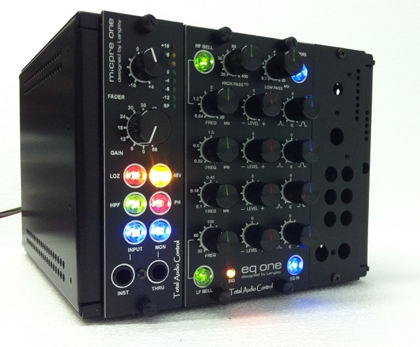
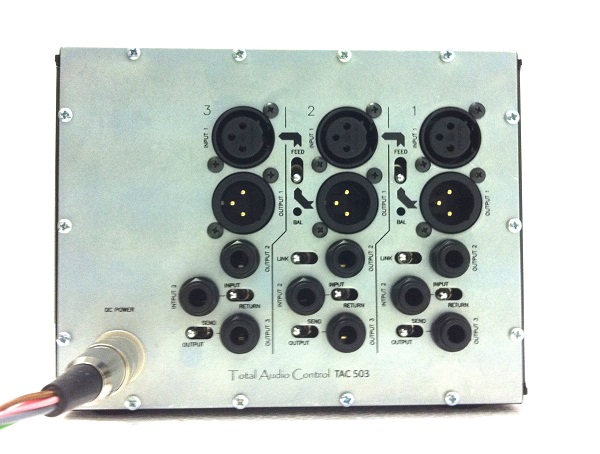
1 SLOT
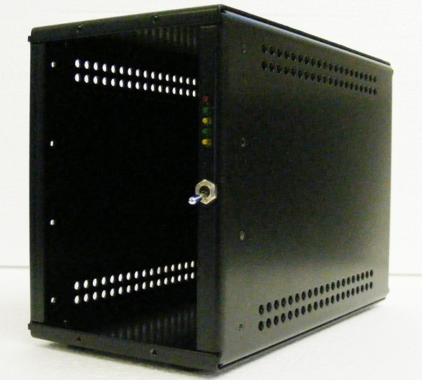
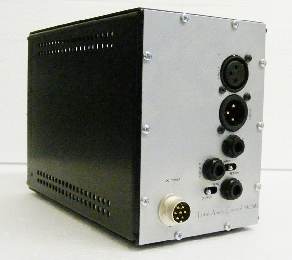
Before getting into the details two important points require to be mentioned.
Firstly all types feature on board status LEDs and an (optional) On/Off switch. The switch simply controls a relay on the floor type power supply eliminating the need to reach out to the back of the rack to turn the power supply off.
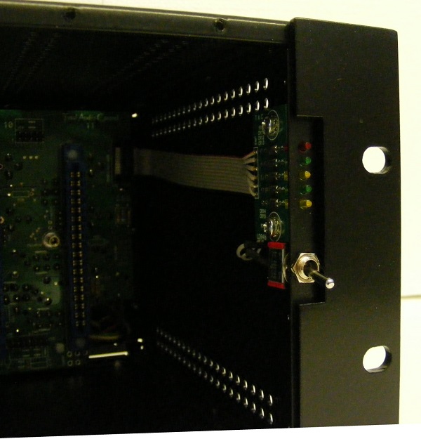
Secondly, (for obvious reason) apart from the 11 slot all the other 6, 3 and 1 slot desktop types are actually 1 slot wider on the Right hand side. This can be seen on the below 3 slot image. The additional fourth slot is fitted with a blank plate.There are two advantages to this.
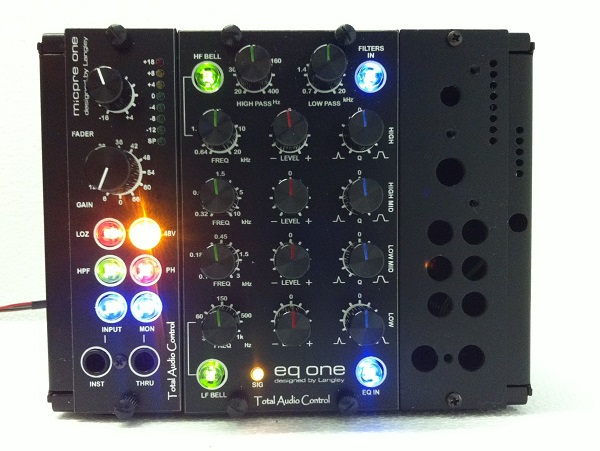
Although it is a mono unit our EQ ONE is double width. So, under normal conditions this would take up the 2nd and 3rd slots. But by placing the double width module on the 3rd slot you will still have the 1st and 2nd slots for two single width modules as usual.
The other advantage is that in the case of using three single width modules you'll have one module space left blank. An on-board power supply can be fitted into this space.
BASIC OPERATION
In this mode you have the XLRs for basic In/Out connections. This is the standard kit with the edge connectors, XLRs, backplane, status LED PCB and the metalwork.
The in/out connections can also be made through the three Sub D25s (at additional cost). The fourth one is left for future use.
ADVANCE OPERATION
In advanced mode each slot is fitted with the additional jack/switch arrangements to form a powerful tool with comprehensive signal routing and splitting for both the studio and live use. The good side of the system is that you can configure each slot to your own taste and/or application. If you require only a single slot to be upgraded then that's what you do.
You can split inputs/outputs and form insert points. All the slots can also be connected in series with the use of their respective "FEED" switch. This basically routes the output of its respective slot to the input of the adjacent one, eliminating the need for patching.
This operation is normally passive and all these functions are set by the on board jumpers
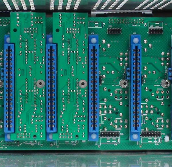
However, in active operation the Balancing card is used in the below image..
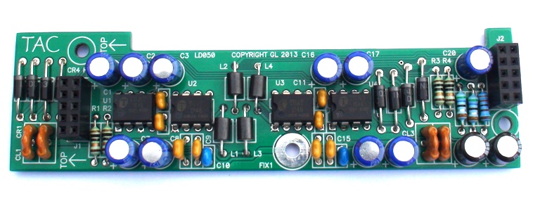
Two slots fitted with the Balancing card.
REAR PANEL CONNECTIONS
As mentioned before the FEED switch routes the output of its respective slot to the input of the adjacent one. In which case all the slots on the rack can be connected in series.
The switches next to their respective jacks are used to set their functions.

INPUT 1 and OUTPUT 1
Basic XLR in/out connections.
INPUT 2
This can be configured as;
PARALLEL INPUT
UNBALANCED INSERT RETURN (passive operation)
BALANCED INSERT RETURN (active operation with the use of BALANCING CARD).
OUTPUT 2
This can be configured as;
OUTPUT SPLITTER 2 (direct)
OUTPUT SPLITTER 2 (through the BALANCING CARD).
OUTPUT 3
This can be configured as;
OUTPUT SPLITTER 3 (direct)
OUTPUT SPLITTER 3 (through the BALANCING CARD)
UNBALANCED INSERT SEND (passive operation)
BALANCED INSERT SEND (active operation with the use of BALANCING CARD).


Available through White Market.
All versions are GDIY 51X, API and Radial compatible.
11 SLOT


6 SLOT


6 SLOT WITH RACK MOUNTING BRACKETS


3 SLOT


1 SLOT


Before getting into the details two important points require to be mentioned.
Firstly all types feature on board status LEDs and an (optional) On/Off switch. The switch simply controls a relay on the floor type power supply eliminating the need to reach out to the back of the rack to turn the power supply off.

Secondly, (for obvious reason) apart from the 11 slot all the other 6, 3 and 1 slot desktop types are actually 1 slot wider on the Right hand side. This can be seen on the below 3 slot image. The additional fourth slot is fitted with a blank plate.There are two advantages to this.

Although it is a mono unit our EQ ONE is double width. So, under normal conditions this would take up the 2nd and 3rd slots. But by placing the double width module on the 3rd slot you will still have the 1st and 2nd slots for two single width modules as usual.
The other advantage is that in the case of using three single width modules you'll have one module space left blank. An on-board power supply can be fitted into this space.
BASIC OPERATION
In this mode you have the XLRs for basic In/Out connections. This is the standard kit with the edge connectors, XLRs, backplane, status LED PCB and the metalwork.
The in/out connections can also be made through the three Sub D25s (at additional cost). The fourth one is left for future use.
ADVANCE OPERATION
In advanced mode each slot is fitted with the additional jack/switch arrangements to form a powerful tool with comprehensive signal routing and splitting for both the studio and live use. The good side of the system is that you can configure each slot to your own taste and/or application. If you require only a single slot to be upgraded then that's what you do.
You can split inputs/outputs and form insert points. All the slots can also be connected in series with the use of their respective "FEED" switch. This basically routes the output of its respective slot to the input of the adjacent one, eliminating the need for patching.
This operation is normally passive and all these functions are set by the on board jumpers
However, in active operation the Balancing card is used in the below image..

Two slots fitted with the Balancing card.

REAR PANEL CONNECTIONS
As mentioned before the FEED switch routes the output of its respective slot to the input of the adjacent one. In which case all the slots on the rack can be connected in series.
The switches next to their respective jacks are used to set their functions.

INPUT 1 and OUTPUT 1
Basic XLR in/out connections.
INPUT 2
This can be configured as;
PARALLEL INPUT
UNBALANCED INSERT RETURN (passive operation)
BALANCED INSERT RETURN (active operation with the use of BALANCING CARD).
OUTPUT 2
This can be configured as;
OUTPUT SPLITTER 2 (direct)
OUTPUT SPLITTER 2 (through the BALANCING CARD).
OUTPUT 3
This can be configured as;
OUTPUT SPLITTER 3 (direct)
OUTPUT SPLITTER 3 (through the BALANCING CARD)
UNBALANCED INSERT SEND (passive operation)
BALANCED INSERT SEND (active operation with the use of BALANCING CARD).


Available through White Market.


![Electronics Soldering Iron Kit, [Upgraded] Soldering Iron 110V 90W LCD Digital Portable Soldering Kit 180-480℃(356-896℉), Welding Tool with ON/OFF Switch, Auto-sleep, Thermostatic Design](https://m.media-amazon.com/images/I/41gRDnlyfJS._SL500_.jpg)


