> Is it normal for transformer-coupled circuits to have phase shifts
Everything has phase shifts.
Nothing is "flat" to infinite frequency.
All roll-offs imply phase shift as well as response droop.
In your other thread.... all transformers ring. The ringing often may be made insignificant with careful choice of source and load impedance (yes, source makes a difference). There are ways to build such impedances into the transformer: use iron wire and get resistance so high you can't see the reactance, use fat laminations and the iron loads the ringing.
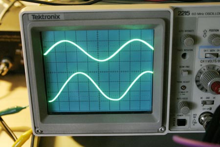
Your photo shows 100KHz ringing. This is, by itself, just not a problem in a well designed system. (It could be a big problem if you also have 100KHz tape-bias leakage.) The "cure" for the ringing is to reduce frequency response. A lower-value load resistor will give the winding stray coupling something to work against, which will droop the top-end. In fact if the amp is designed for 600 ohm loads, you should not complain if it rings at no-load. Since many modern inputs are much higher than 600 ohms, it is a point to check: in some designs you may want to hang 2K across the output permanently, in others you may have to keep a 600 ohm dummy load handy (on a switch) and use it when driving hi-Z loads, omit it if you ever meet a true 600 ohm input.
Oh, and you really shouldn't overdrive a single-ended transformer-coupled amplifier when it is not loaded. Just like a relay coil, or the spark-coil in your car, when the transistor is driven into cut-off the coil kicks-back and spikes up to a very high voltage. I could imagine this amp kicking to 250, even 400V. That's marginal for winding insulation. It is also way over the rating of the 2N3055, though one reason Rupert used such a fat device is because it can usually survive all the energy that the transformer can dump.
> I guess, the slew rate isn't fast either
Well, I can't see the scope settings. But clearly it is much-much faster rise-time than is needed to deliver high-level sines at 10KHz, and probably at 20KHz too. Unless you are recording dog-whistles, that is usually more than enough slew.
Don't expect "perfect" waves out of any single-ended transformer coupled amplifier. But the traces you show, at quite high signal levels, look fine to me.
You really should set the output stage bias. If I recall, somewhat under 100mA. Rupert's factory spec called for a specific load, test tone, and trim for maximum output before clipping without excess heat.