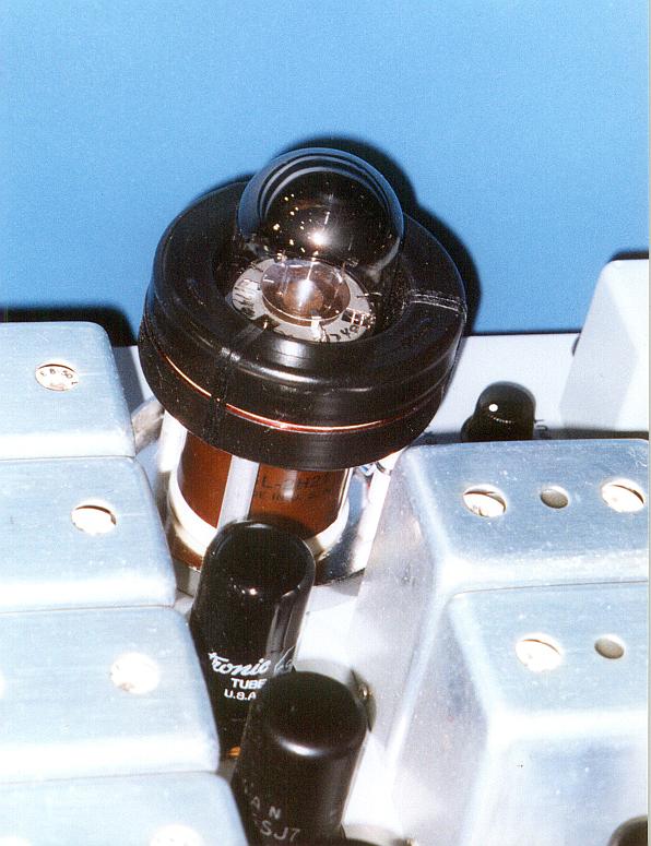
Tube Compressor Idea?

GroupDIY Audio Forum

Help Support GroupDIY Audio Forum:

This site may earn a commission from merchant affiliate links, including eBay, Amazon, and others.

dale116dot7

Well-known member
Joined
Jun 5, 2004
Messages
875
Location
Calgary, Alberta, Canada
Has anyone tried this or can they tell me why it won't work? 6JH8 sheet-beam tube. Control voltage goes to grid, audio signal goes to the two deflectors. Output is transformer-coupled off the plates. There should be very little CV feedthrough as the grid should be pretty matched. From the curves it should take about +/- 20 volts of audio on the deflectors to make it work. Thoughts?
 
The 6JH8 is an interesting tube. The deflectors move the sheet beam between two plates it the tube. It seems like an on-off kind of effect, though. I am not sure that changing the bias on the deflector is going to vary the current in the beam other than all or nothing. It is a very fast tube, though, so a PWM approach would not be out of the question, for example like the Crane Song Trakker compressor. In the case of PWM, though, you would probably want to apply the signal to the actual control grid. I think with the two plates, too, you could do some kind of balanced out with the unwanted harmonic content getting dumped in a transformer, possibly. Do we know how much space there is between the plates? I could always "CJ" one and find out, I suppose. The data sheet also recommends magentic shielding to protect the beam from interference.
 
[quote author="burdij"]I could always "CJ" one and find out, I suppose.[/quote]

Ha! CJ has become a verb. :green: And, what the hell, an adjective, too .... "Why, how CJ of you." The man is officially a legend.

As for the 6JH8, here's a datasheet link for reference: 300kB PDF

If the plates are all or nothing, on-off, couldn't you parallel the plates? That would give you an always-on beam with varied intensity. Of course, using one plate for each polarity has possibilities.

Ahhhh, I was going to ask what was meant by "balanced deflectors," but then I spotted this note:

"Deflector switching voltage is defined as the total voltage change on either deflector with an equal and opposite change on the other deflector required to switch the plate current from one plate to the other."

EDIT: Realizing I wasn't making any sense. I shouldn't post in the morning.
 
Looking at the chart 'Average Transfer Characteristics', the movement of the beam from one plate to the other seems quite linear to me. At zero differential, the currents are split evenly. I wanted to avoid putting any signal on the control grid - just the control voltage. Since it's a pentode at heart, the current should remain pretty constant and the sum of the current at the two plates should remain equal - greatly reducing the 'Altec Thump', in theory. Also, since only about 10 volts of control signal is required (similar to the Altec) but the audio voltage is not superimposed on it, distortion should be more manageable, and more headroom should, in theory, be available.

I thought this would be a neat approach in that you don't really need to match two tubes to get rid of CV feedthrough. I have a compressor that's a hybrid between a 436C and a UA175. Perhaps I'll replace the 5670W with one of these and see what happens. It might work... I'll let you know after the weekend.

-Dale
 
Skipwave - thanks for the datasheet link. The only sheets I had didn't have any curves.

It appears that there is no space between the plates, looking at the transfer curve, and that between 0 and -4 v on the control grid the plate current has a remarkably linear relationship, within the -20 to +20 v deflector voltage range, to the deflector voltage. Nice catch Dale. Time for some experiments, I think . . .
 
For accurately matching balance between the two plates, you should be able to move the beam by the means of an external (adjustable) permanent magnet :razz:

Jakob E.
 
Now we're getting somewhere. I want to see a mechanically operated, permanent magnet controlled, tube variable gain stage.
 
Why not generate a direct electromagnetic field, i.e. by a coil?

"Magneto-valve compressor"

..could be a part of a fridge with that name..

:razz:

Jakob E.
 
It gets complex when you introduce even just static magnetic fields.

One of the early Hubble instruments was a 512-element linear optical sensor called a Digicon. A photocathode emitted electrons, and they were accelerated with about 30kV to slam into silicon diode targets and produce an avalanche of additional charges large enough to be easily counted as pulses by the preamps/discriminators (yes, there were 512 preamps!). Each photoelectron emitted was focused by very precise permanent magnets outside the vacuum envelope to land on corresponding regions of the target; iirc each underwent a spiral path with three turns (recall the equation for electron trajectories in a B field involves a vector cross-product...).

I overheard a conversation at an all-UC astronomy meeting between two people, one of whom worked for the contractor developing the spectroscopic system for which the tube was a detector. The guy said things had been going fairly well, except that they had lost a tube recently while testing. What had happened was they turned the lights on after the power supply for the 30kV had been turned off. Unfortunately they didn't realize that the voltage took a while to fully decay. With the few kilovolts left or so the electron barrage from the photocathode was no longer focused, banged into regions around the diode target, and knocked out stuff that then diffused back and "poisoned" the photocathode.

The tubes cost about 250k$ iirc, and that was back when money was still worth something :razz:

They added a fast-off crowbar circuit to the HV power supply after this incident.
 
gecoil.jpg

Phasitrons were cool. They used an audio signal on the magnetc field around the tube to Phase modulate an early FM transmitter (late 40's).
http://www.w9gr.com/phasitron.html
 
> Why is grid2 hardwired to the filament?

They have 10 pounds of junk in a 9-pound bottle. Some two functions must share a pin. The path they choose requires one end of the heater to be grounded. Series-string TV sets always have a tube at the bottom, though usually the chroma isn't your first choice.

In high quality audio, a grounded heater-end is bad news for AC heat. With DC heat it may be "natural".

>Control voltage goes to grid, audio signal goes to the two deflectors.

In your proposed connection, the tube does look linear and ample output down 20dB-26dB of gain reduction. The current will fall the same amount, which is better than the near square-root curve of typical tubes in the classic Gm VCA. But current still falls a lot. Resistor loading would give huge common-mode shift. Current starts high, so it is a non-trivial transformer design, even if the balance stays "good".

I bet drive signal must be well balanced or it loses focus and those sharp curves degrade. "All" electrostat CRTs use push-pull deflection to preserve focus... actually I have two elderly 'scopes with single ended drive, and the focus and trapezoiding is quite apparent. The output of this tube is in effect the shape of a (1-D) CRT trace, so poor deflection balance will give sloppy output.

That also seems to rule out use as a long-tail phase splitter for push-pull power amp grids, though such schemes often tolerate high unbalance well.

There is yet another way to use this tube. Apply signal to G1. Swing it from zero to -4V (-2V bias) or add a cathode resistor for more linarity. One plate goes to load. Other plate idles, or is used as NFB to the input. Waggle the deflection electrodes. It is a current-steering VCA, often found in chips. In this form it has large DC shift with control, but you can use two push-pull, and then sum the "idle" plates to get a no-signal DC current the inverse of the DC current of the signal plates' current and null the shift.

The 6AR8 text mentions offset deflection errors. In the original switching operation, that just means you overdrive a little more. I gather that the exact shape of the diagonal lines is NOT essential to chroma matrix duty, and may not be as neat and symmetrical as the pretty picture.

This deflection control is NOT like any "normal" tube amp. It seems superficially like a GM VCA, but in the classic VCA the two tubes work independently. In the sheet-beam, there is really only one electron highway but it bends to two exits.

When you poke at it long enuff, you wonder.... is this really a tube circuit? Or has it been hacked so "good" that it may as well be done in transistors, and better with a chip?
 

Latest posts

Back
Top