turret (not p2p) pultec questions

GroupDIY Audio Forum

Help Support GroupDIY Audio Forum:

This site may earn a commission from merchant affiliate links, including eBay, Amazon, and others.

baadc0de

Well-known member
Joined
Jul 9, 2009
Messages
797
Location
Europe
Hi all,

I'm looking to make two p2p pultecs based on this design and layout
http://www.recproaudio.com/diy_pro_audio/pultec_eqp1a.htm

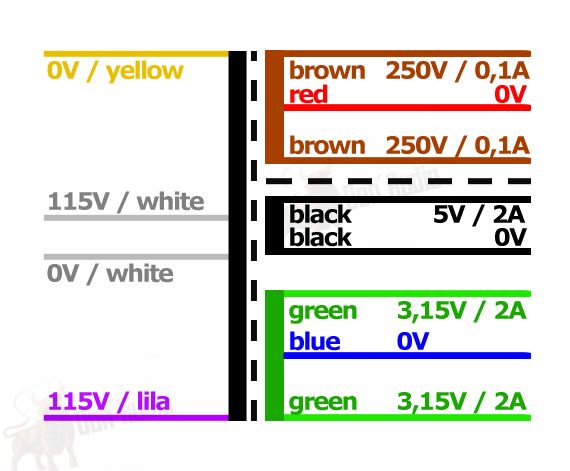
I have sowter signal level transformers and am now pondering what to do with power. I wanted to go with the 370CAX, but the site says:
Update: It has been brought to my attention that the Hammond 270CAX power transformer is no longer made with a center tap for the 6.3V winding. To accurately float the heaters, you will need a transformer with a 6.3VCT. Earlier 270CAX transformers with 6.3VCT might still be available from some sources such as Angela Instruments. Sowter also has the proper iron.

The shop where I wanted to buy it from (http://www.tube-town.net/ttstore/product_info.php/info/p1014_Hammond-370CAX.html) lists the heaters as being CT. Just to be on the safe side, is this power transformer appropriate?

Second, I wanted to modify this pultec design to have a switchable high pass filter (no need for steep curves here). How would one go about designing this feature? I have talked with an EE friend of mine and he said that it's hard to predict how the circuit will react, so it would be best to build the rest in its entirety and test it, then add on the HPF by experimenting with values.

Is this truly the best way to go about it? Can't I precalculate the filter R/C values?
 
> To accurately float the heaters, you will need a transformer with a 6.3VCT

Bosh. Wire two 100 ohm resistors to ground. If your tubes are good, that is exactly the same as a CT; if you have a bad heater leakage you will have problems in any case.

The best way is a 100 ohm 1W balance pot, which used to be common, but is now rare.

> Can't I precalculate the filter R/C values?

In this case the EE has told you right.

It "can" be pre-calculated. It is a very devious circuit. I sense that you are not yet able to do it, so you will have to pay someone for hours of hard thinking. It would be easy to tinker once built. Especially on turret: tack-solder parts to the top of the turrets so you can easily change them until happy.
 
Take a look here:

http://www.hammondmfg.com/263.htm

I'm counting about 3 or 4 good candidates starting with the 270AX.  Note: You can run the small voltage pilot light off the 6.3V string.

I think the 200 series area little better priced than the 300 and up.

I built my pair with using the standard 100r pair to ground as a CT. No problems.


High pass on a Pultec?    See if there are some published curves of the Low attenuator's action. It does a pretty good job. Just wondering why the need.
 
peterc said:
I would have thought that turret construction is Point to point?

What would be the difference between turret & tagstrip?


Point to point is done ideally from socket pin to socket pin + jacks. In reality you nearly always need a  terminal strip or two.

Turret is close and if you're good you could possibly net the difference in terms of extraneous runs of wire (stray capacitance).

Component layout could run into problems in either case. Turret can solve those issues in some cases. All related to practical space issues and weighing trade offs.
 
lassoharp said:
Take a look here:

http://www.hammondmfg.com/263.htm

I'm counting about 3 or 4 good candidates starting with the 270AX.  Note: You can run the small voltage pilot light off the 6.3V string.

I think the 200 series area little better priced than the 300 and up.

I built my pair with using the standard 100r pair to ground as a CT. No problems.


High pass on a Pultec?    See if there are some published curves of the Low attenuator's action. It does a pretty good job. Just wondering why the need.

I was under the impression that the 2xx series was USA primaries and the 3xx series was international primaries. I'll look into it, but I need the EU 220/230v primary voltage anyhow. Thanks for the tips.

Allright, the 2x100r to ground should be ok for me as well, then!

Why the high pass on a pultec? A bit because I can, more sensible reason is I (from experience with other EQs) like to interact a rather high set HPF with a LF boost under it with a peak or shelve. Now, I never really used a hardware pultec before or the UAD plugin, so I'm not sure how this practice of mine will carry over or whether it will be redundant. I had some fun with the Nomad Factory plugin, but still preferred the HPF+low boost vs. low cut and low boost. But that's a plugin. Won't hurt for a few more options, and it will be 100% bypassable anyhow, so there's no danger of ruining anything.
 
I forgot about the 220 int voltage.  300 series should have several options there as well.

Pultec has the boosting/cutting interaction.  Might be interesting to use a HP with different slope/cutoff point in conjunction.

Good Luck with the build!
 
baadc0de said:
Hi all,

I'm looking to make two p2p pultecs based on this design and layout
http://www.recproaudio.com/diy_pro_audio/pultec_eqp1a.htm

Update: It has been brought to my attention that the Hammond 270CAX power transformer is no longer made with a center tap for the 6.3V winding. To accurately float the heaters, you will need a transformer with a 6.3VCT. Earlier 270CAX transformers with 6.3VCT might still be available from some sources such as Angela Instruments. Sowter also has the proper iron.

Hello all
i also looking to make two 2P2 pultecs with the same layout. Buy without any mods to the filter.

For the power xfm, i think this one is nice for 220/230 primary (35 euros)
http://www.don-audio.com/Audio-Toroidal-Transformer-pri-230V-sec-500Vct-01A-63Vct-02A-5V-2A
12_2.jpg


but i don't know if we need 100r pair to ground. maybe someone here can ask the question ;)

Creal
 
baadc0de i also start this project, what did you think to make a special post on the lab ?

I have ordered some part but missing the xfrms and the knobs...


If you want to, we could. I only opened this thread to pose questions about the design before actually building it (that's why it's in the drawing board). Having received the information and feeling that I have obtained the necessary info, we could just move it to the lab and continue there, why not..
 
Well, this is rather unfortunate...

the graph up there says 3.15 - 0 - 3.15

the actual transformer says 0 - 3.15 - 6.3

can I still use it? And connect the 3.15 to the centertap point? 0-6.3 obviously go to heaters..

I'm using this schemo

http://www.recproaudio.com/diy_pro_audio/diy_files/eqp_1a/eqp-1a_schem.jpg
 
baadc0de said:
Well, this is rather unfortunate...

the graph up there says 3.15 - 0 - 3.15

the actual transformer says 0 - 3.15 - 6.3

can I still use it? And connect the 3.15 to the centertap point? 0-6.3 obviously go to heaters..

I'm using this schemo

http://www.recproaudio.com/diy_pro_audio/diy_files/eqp_1a/eqp-1a_schem.jpg

you can use it. 3.15 is the centertap.
 
hop.sing said:
you can use it. 3.15 is the centertap.

Thanks! That's what I thought and how I wired it, but wanted an opinion anyway.. I hope to post a pic today or tomorrow before I turn it on. First build that's not a PCB for me, very nervous..
 
baadc0de said:
Well, this is rather unfortunate...

the graph up there says 3.15 - 0 - 3.15

the actual transformer says 0 - 3.15 - 6.3

can I still use it? And connect the 3.15 to the centertap point? 0-6.3 obviously go to heaters..

Just use the green wires and don't connect the CT, you'll have 6.3v
 
creal said:
baadc0de said:
Well, this is rather unfortunate...

the graph up there says 3.15 - 0 - 3.15

the actual transformer says 0 - 3.15 - 6.3

can I still use it? And connect the 3.15 to the centertap point? 0-6.3 obviously go to heaters..

Just use the green wires and don't connect the CT, you'll have 6.3v

So, just don't connect the CT to the PS.. I'm curious, given the two options, which one would be inherently better and why?
 
baadc0de said:
creal said:
baadc0de said:
Well, this is rather unfortunate...

the graph up there says 3.15 - 0 - 3.15

the actual transformer says 0 - 3.15 - 6.3

can I still use it? And connect the 3.15 to the centertap point? 0-6.3 obviously go to heaters..

Just use the green wires and don't connect the CT, you'll have 6.3v

So, just don't connect the CT to the PS.. I'm curious, given the two options, which one would be inherently better and why?
I just look the schematic
Connect the two green wire in 3 and 4 pin opf the 6X4 and the CT on the .3cap/62Kres
 

Latest posts

Back
Top