turret (not p2p) pultec questions

GroupDIY Audio Forum

Help Support GroupDIY Audio Forum:

This site may earn a commission from merchant affiliate links, including eBay, Amazon, and others.
creal said:
I just look the schematic
Connect the two green wire in 3 and 4 pin opf the 6X4 and the CT on the .3cap/62Kres

Yup, I did that, but wanted verification if the 0v CT on the website is "compatible" with the 3.15v CT on the realworld trafo. I guess it is and I'll see if it works that way. Relative voltage is the same (3.15v to either of the heater legs).
 
So, just don't connect the CT to the PS.. I'm curious, given the two options, which one would be inherently better and why?

You generally always need some reliable reference to ground for AC filament circuits.  Even in the Pultec circuit the CT is connected, but referencing ground at an elevated potential.  I can loosely say ( I don't fully understand that circuit) that with +40V on the 12AU7 cathodes, that is likely why they chose to "float" the filament reference above ground.

The pair of pultecs that I built did just fine with a CT only (no floating circuit).  If it's convenient, try a CT-to-ground only first and compare hum level with the floating arrangement on the schematic.

You can also try using a 100-200ohm pot connected across the filaments - wiper to ground if either of the above methods prove to be inconsistent.


Second, I wanted to modify this pultec design to have a switchable high pass filter (no need for steep curves here). How would one go about designing this feature? I have talked with an EE friend of mine and he said that it's hard to predict how the circuit will react, so it would be best to build the rest in its entirety and test it, then add on the HPF by experimenting with values.
I built a pultec with sowter interstage and output transformers recently and am right now experimenting with a high pass filter in the circuit. Inserting a 0,22uF cap right in front of the interstage tranny gives you a steep cut at around 40 Hz but with a heavy resonance of about 8 dB before. A 0.1uF does The same at ca. 80 Hz (obviously).
Combined with the regular low cut of the circuit, that arrangement gives a few options that are not possible with the stock circuit and it sounds pretty interesting, but I am not sure if it is worth implementing. That way it is pretty much a one trick pony.
If there would be a way to tame the resonance a few dB, it would me much more useful. A slight resonance is pretty cool, I think. Next thing I will try, will be a cap after the input transformer, but I gues it will be a pretty boring 6dB octave high pass, but let's see.
Tobias
 
  As a quick aside: baadc0de-- you said it yourself: "Relative voltage is the same...".  Someone with specific knowledge of how the transformer would be hooked up would label the heater center-tap "0", as the typical connection would be to ground AKA 0v.
An EE major (a pot shot was taken earlier, why not continue the tradition), following typical labeling practices would put a zero on the bottom of the winding schematic and work their way up to 6.3v.  To the EE major's credit, I think this view is a little more open to interpretation-- I think for most beginners it is easier to leap from "0 - 3.15 - 6" to "3.15 - 0 - 3.15" than vice versa.  "3.15 - 0 - 3.15" seems specific and somehow inflexible.  I suppose the mark of any great creator is to be able to ignore conventions and see only results, but I know I'm certainly not there yet and I thought I'd clear things up for those floundering in the dark with me.
  Anyway, baadc0de, you figured it out but I thought I'd expand at great length and pomposity.
 
Hello guys...

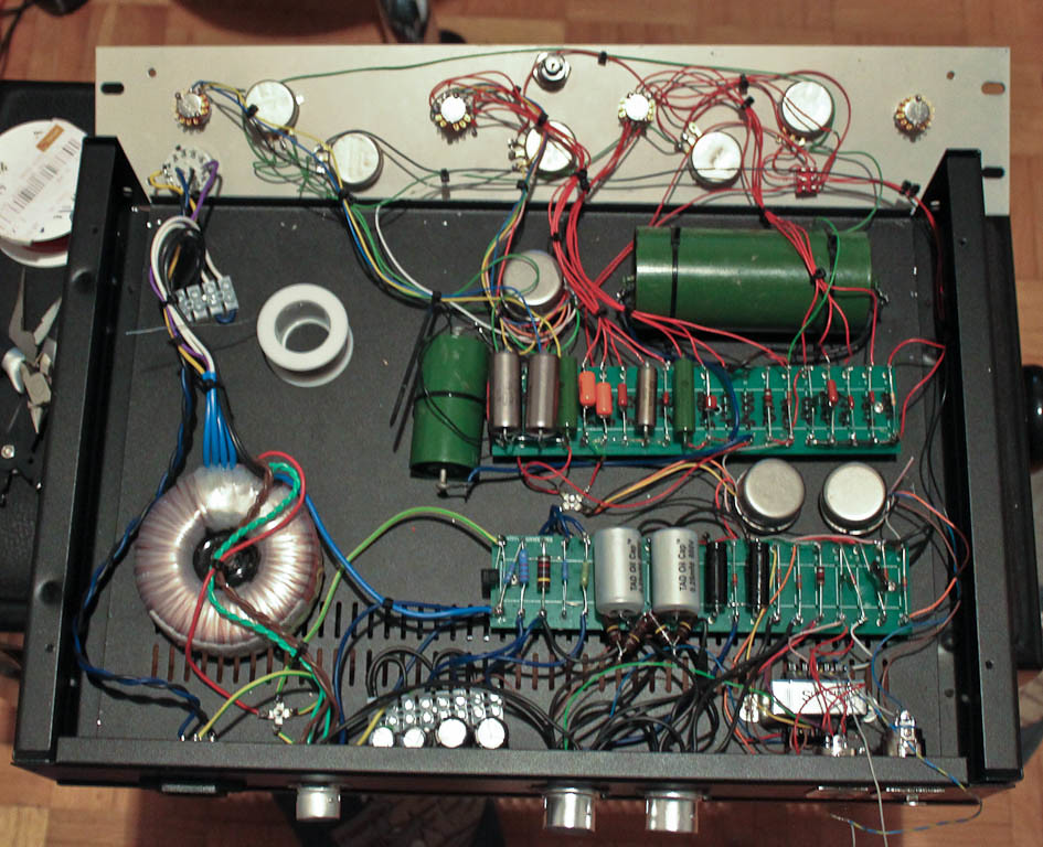
I managed to get this over with..
5291456548_4d18519517_b.jpg

This is before the pilot lamp was wired and a few other tidbits..

However, it's not passing signal. I'm getting a bit of hum on the output and the passive controls work with modifying this hum (the low shelf being especially potent), so it seems the EQ and amp sections are working and I'm not getting signal to the passive section at all. Am I right in assuming that (possibly) reversing the hot and cold on the input would just mean a polarity inverse with the sowter input trafo? Though, I might have changed hot and ground... we'll see :)
 
There's also a pink wire on the sowter input that is the center tap on the secondary, and I currently have it connected nowhere. Should it go to ground? EDIT: Bypass, for example, is working as expected.
 
Ok, passes signal now, but at -40dBFS on my TC konnekt 48 (no idea how much that is in dBU). All of the EQ controls work and sound great.. I just want my gain now :)
 
Ok, I've got no idea what is wrong... pin 2 on the output is swinging 8Vpp on my scope and pin 3 is showing as flat. In my interface I'm getting very low signal (though nicely EQ'd) and some noise. EDIT: I'm an idiot. Stuff works better when it's plugged in (all the way)... jeez. Works GREAT!!!! Thanks for all the advice in this thread and cayacosta for the layout.


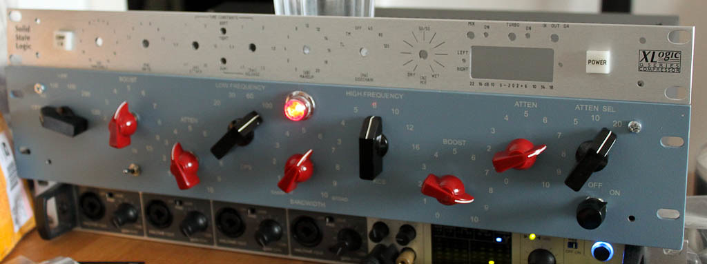
Here it is, happily churning away at some random overheads or something.. going to try it at vocal tracking soon :)
5292504597_bd61edc249_b.jpg
 
baadc0de said:
works better when it's plugged in
Congrats on your build and troubleshooting skills!
Some huge soviet capacitors too!
I bet it sounds awesome!
 
Thanks! I'm really impressed by its noise performance.. My konnekt interface has -95dBFS self-noise, and the pultec (working from the D/A output already, so it's amplifying konnekt's D/A noise) parks at -80dBFS. That's really quiet for me. The soviet caps sound nice.. I like those a lot. There was a shootout of coupling caps and those struck me as best, better than anything else at the shootout..

About the high boost, what kind of caps do people suggest for a colorful tracking box (this isn't for mixing, I'll do Igor's neve pultec for that)? I've heard WIMAs kicked around a lot and styro's? I currently have installed some orange drops, some panasonic SMFs, some xicon greenies.. basically stuff that was lying around.
 
Well, those soviet caps are hard to beat, IMO. I liked those the best, smooth! I think polyprop caps (wima, etc) sound somewhat harsher on highs. There's also soviet teflon caps you can try (FT-3, K72-XX) those supposed to be ultimately clean. Then there's soviet silver mica - SG something, for "brighter" highs...
 
> An EE major ... would put a zero on the bottom of the winding schematic and work their way up to 6.3v.

That's how a transformer winder thinks.

The design leads to a volts-per-turn value. Say 0.1V per turn.

We want one 6.3V winding with half-way tap. Half is 3.15V.

No turns is zero volts.

From there, lay 31.5 turns, call it "3.15V". Lay another 31.5 turns, another 3.15V, call it "6.3V".

I want to wall-paper a 34" wide wall. Paper comes 17". Do I say 0" 17" 34"? Well, you usually pull a center-line and work each way so any slop is equal on both sides. Now it is 17" east - center - 17" west. Or with +/- numbers, -17"/0/+17".

Sometimes you have to think as sharp as a paper-hanger.
 
Hi everybody,
BaadcOde, Congratulation for your EQ, very beautiful.
Where do you have your frontpanel?

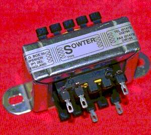
I have doubts about the wiring of the 9530-x, I used this pinout.
9530.jpg

Can you confirm me?
Now, i need to wire the filter part before the first tests
Here is a picture of the unit.

normal_photo.JPG

Work in progress
 
Ugh, I've got the colored leads version... I have another one I haven't installed yet, so I'll take a photo of it when I get home later today. Don't know how much good that will do, but it can't hurt...
 
baadc0de said:
Ugh, I've got the colored leads version... I have another one I haven't installed yet, so I'll take a photo of it when I get home later today. Don't know how much good that will do, but it can't hurt...

Many thanks, i think that's will help me to find the correct wiring.
Can you measure the values of resistance for the Primary and secondary?
 
Second, I wanted to modify this pultec design to have a switchable high pass filter (no need for steep curves here). How would one go about designing this feature? I have talked with an EE friend of mine and he said that it's hard to predict how the circuit will react, so it would be best to build the rest in its entirety and test it, then add on the HPF by experimenting with values.
I built a pultec with sowter interstage and output transformers recently and am right now experimenting with a high pass filter in the circuit. Inserting a 0,22uF cap right in front of the interstage tranny gives you a steep cut at around 40 Hz but with a heavy resonance of about 8 dB before. A 0.1uF does The same at ca. 80 Hz (obviously).
Combined with the regular low cut of the circuit, that arrangement gives a few options that are not possible with the stock circuit and it sounds pretty interesting, but I am not sure if it is worth implementing. That way it is pretty much a one trick pony.
Now I tried the cap in front of the filter circuit (right after the input transformer) and with 4,7 uF I had a gentle 6dB octave filter with a -3dB point at 40 Hz.
Might be useful for tracking and cleans up some rumble if boosting low freqs but overall does not sound very inspiring or special for me. I can do the filtering at the Micamp if needed.
 
creal said:
baadc0de said:
Ugh, I've got the colored leads version... I have another one I haven't installed yet, so I'll take a photo of it when I get home later today. Don't know how much good that will do, but it can't hurt...

Many thanks, i think that's will help me to find the correct wiring.
Can you measure the values of resistance for the Primary and secondary?

I email sowter about this a while ago. They sent me this:
 

Attachments

  • 9530x.pdf
    21.8 KB · Views: 24

Latest posts

Back
Top