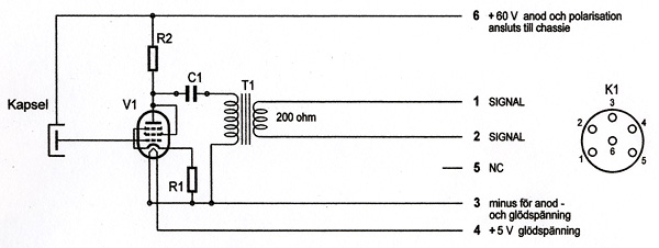
1) massive 105V supply like original but more current, 2) independent 5V heater, but dummy 105V filament supply for bias, 3) small 105V supply with small 5V heater which doubles as a bias supply.
1) Are you suggesting I use the original u47 schematic, but deliver more current (470mA vs. original 50mA) from the PSU? I would need some way to drop the 36V to 4.95 for the heater, correct? Would I then also use the "dummy load" I initially suggested to divert 31.05V to ground?
2) Are you suggesting creating a parallel, independent power supply of 5V with 470mA from within the PSU, down one of the unused cable wires (i.e. pins 3 or 6) and deliver that to the heater while the filament gets the supply from the original supply coming in on pin 5? What happens to that pin 5 current and voltage when it's no longer being used by the heater? Will I have to make other considerations there in terms of resistor or capacitor values?
3) I guess I'm a little confused as to what a bias supply is. Is it just the voltage applied to the filament in the tube? I don't understand how the bias can be either 105V (as suggested in #2) or 5V (as suggested in #3). I understand that the two areas the VF14 and the EF14 differ are in heater voltage and heater current required. So I guess it's a little fuzzy to me where and how the bias fits in and is applied.


![Soldering Iron Kit, 120W LED Digital Advanced Solder Iron Soldering Gun kit, 110V Welding Tools, Smart Temperature Control [356℉-932℉], Extra 5pcs Tips, Auto Sleep, Temp Calibration, Orange](https://m.media-amazon.com/images/I/51sFKu9SdeL._SL500_.jpg)


