trans4funks1
Well-known member
- Joined
- Feb 4, 2013
- Messages
- 328
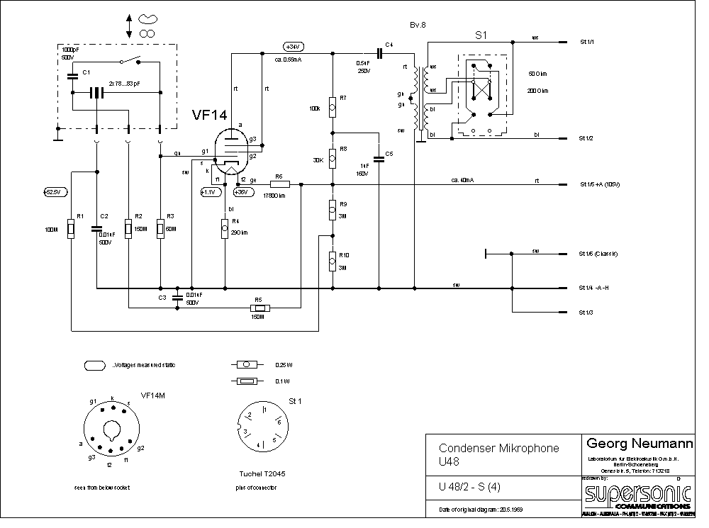
I've been looking at the U48 schematic because I am interested in figure 8 patterns. I have a few questions regarding the polarization voltage. Some of the questions relate to the U47 topology too. I think they are pretty basic questions but I realize I don't fully understand what is going on.

For the polarization of the back plate there is 105vDC on one side of R9.
R9 (3Mohm) and R10 (3Mohm) act as a voltage divider and get the voltage down to 52.5vDC.
Question 1: What happens at or across R1 (100Mohm)?
For the polarization of the rear capsule there is 105vDC on one side of R5 (150Mohm) and there is another resistor, R2 (150Mohm) in series as you trace the circuit to the rear capsule.
Question 2: What is happening at R5 and R2? I assume that the voltage at the rear capsule should be approximately twice that of the back plate. If the voltage at the rear capsule is 105vDC(?) how can I quantify the voltage drop across the resistors?
Is the fact that current draw is very small a factor?
Thanks for any explanation you can offer.


