Using input & interstage transformers in a balanced passive mix bus design

GroupDIY Audio Forum

Help Support GroupDIY Audio Forum:

This site may earn a commission from merchant affiliate links, including eBay, Amazon, and others.
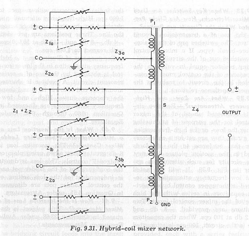
MORE schematic of the 50 :

86590127.jpg


520508119.jpg
 
Awesome, vari-mu. Many thanks! I also saw your other post and downloaded that 'sound mixer' excerpt, really good stuff. Will adopt & adapt...
 
Throwing all the secondaries in parallel seems to defeat the loss-less sum theory.

I guess they had their reasons, since nobody would give away level when gain was so dear.

JR
 
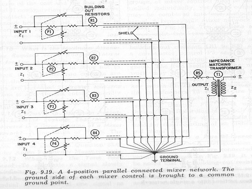
Working to absorb and process these insights, and came across this in some parallel (sorry) research....

Quoted from Steve Dove's Console section in the 2nd ed Audio engineers handbook;

"22.11.7 Balanced Mixing
The earliest form of signal mixing consisted of directly paralleling the sources, which were generally medium- impedance (nominal 600 !l) and balanced. This form of passive balanced mixing persisted until semiconductor electronics and the easily achieved zero impedance tran- spired. The balancing was done entirely by transformers: again. things that have fallen at least partially by the wayside."

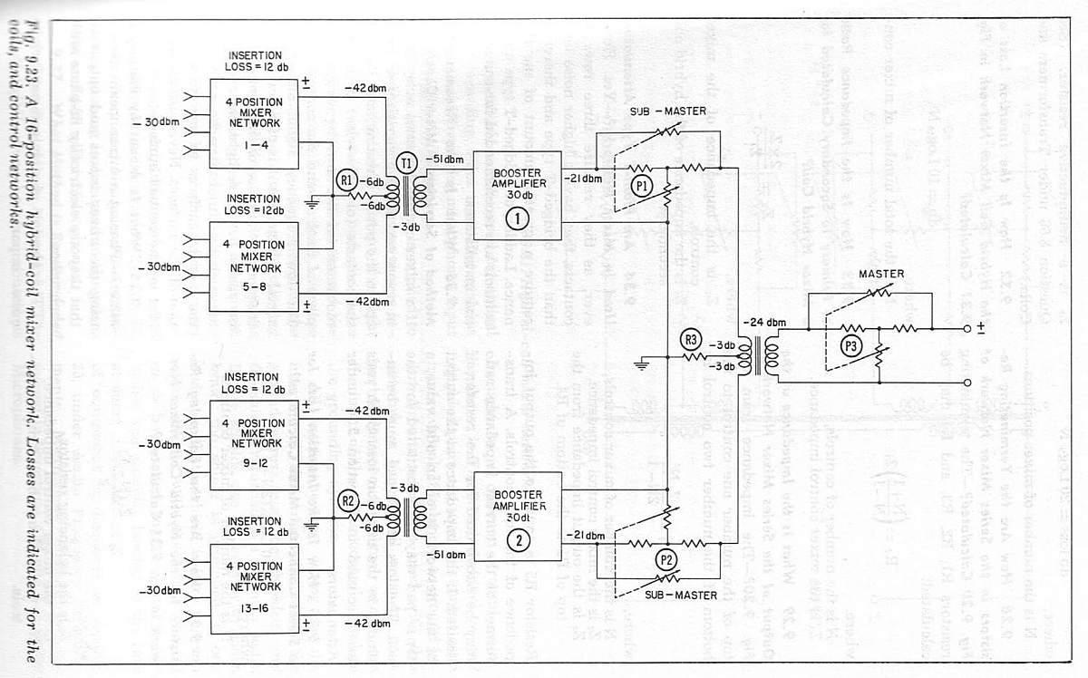
regarding the schemos vari-mu has posted, it seems the UTC version is closest in principle to what I'm after. 

the next "hybrid coil" schematic from the 'Sound Mixer' excerpt uses a combination of resistor mixing and hybrid coil mixing; ie, the first 4 inputs are mixed with resistors (causing insertion loss, as expected) and this submix then drives the primary of the hybrid coil, transferring signal to the secondary with -3db of loss.

That UTC 50-60 device is fascinatingly simple, and I also wonder how it sounds. -12db loss seems less than a purely resistive approach, but I wonder to what extent this loss is due to the resistance elements, rather than the transformer elements.

Newb questions:

1. would I be correct in inferring that the 68-2800-68 Resistors on each A20 are for loading the secondary to deliver optimal frequency response? (zobel network)

2. and the 330r act as mix resistors within the paralleled secondary network?

 
quantyk said:
That UTC 50-60 device is fascinatingly simple, and I also wonder how it sounds. -12db loss seems less than a purely resistive approach, but I wonder to what extent this loss is due to the resistance elements, rather than the transformer elements.
Purely resistive mixing would give only 9dB attenuation.
1. would I be correct in inferring that the 68-2800-68 Resistors on each A20 are for loading the secondary to deliver optimal frequency response? (zobel network)
They are indeed there for properly loading the secondary of the transformer, which has two roles:
a) Ensuring correct frequency response
b) Producing the proper input impedance to the inputs. The input impedance is the reflected impedance of the secondary load. Pure resistors are not a Zobel network. A Zoble network is a way to linearize the frequency response without loading the circuit. Pure resistors actually load the circuit, making the input Z 600r.
2. and the 330r act as mix resistors within the paralleled secondary network?
The mixing resistor is a combination of the source impedance reflected to the secondary, the attenuator's equivalent resistance and the 330r.
The resulting impedance at the junction of the three 330r is about 300r. That's why they added the final 330r to provide a proper 600r source impedance for the final xfmr.
For all these reasons, there is 3dB more attenuation than the strict minimum.
BTW, please note that the 12dB attenuation figure is for 600r source and infinite-impedance load. When used with 600r sources and a 600r load, the total attenuation is 18dB.
 
Working on a schematic/simulation of an adaptation of the UTC circuit, and will post for comments/review shortly. I'm hoping to use the UTC circuit as a basic template and expand/adapt for this application.

I've attached an attempt to redraw the schematic, and I'd appreciate a friendly review to make sure I've got the functional circuit & calculations right, as interpreted from the UTC circuit posted by vari-mu.

thanks again 'abbey', john, cj, vari-mu, gyraf, balljon & prr for your help with this, and to any diy folks who share insight on this.


Assuming a reflected load of 600 from the input primaries, I calculated that the input TF secondary would be in series with the 68r resistor (668 ohms), and this is in parallel with the 2700r, for an equivalent series value of 535 ohms. (1/(1/668)+(1/2700)).

This value, in series with the 68r and 330r resistors, makes for a bus impedance of 311 ohms, as Abbey pointed out. (1/(1/933)*3), which, in series with the 330r before the output primary, creates a load of roughly 600 ohms reflected to the output secondary.

Is this approach correct?

To adapt the design then, I would need to satisfy the required loading of the input secondaries and match the optimal overall buss impedance for the output transformer to the mix amp, right?

From what i understand, MOSFET amps can have fairly high impedance inputs, so I can probably work with the repeat coil transformer to provide a good input level for the mix amp.

The other factors would seem to be:  finding the right termination load for the tamura transformers, and determining the input impedance for the 10852 amp card. 

any thoughts and insights greatly appreciated.

cheers


cheers,

AK


Attachments

  • TMIX-UTC.pdf
    29.5 KB · Views: 25
quantyk said:
Working on a schematic/simulation of an adaptation of the UTC circuit, and will post for comments/review shortly. I'm hoping to use the UTC circuit as a basic template and expand/adapt for this application.

I've attached an attempt to redraw the schematic, and I'd appreciate a friendly review to make sure I've got the functional circuit & calculations right, as interpreted from the UTC circuit posted by vari-mu.
If you want, I can post the .asc file for LTSpice simulation.
Assuming a reflected load of 600 from the input primaries, I calculated that the input TF secondary would be in series with the 68r resistor (668 ohms), and this is in parallel with the 2700r, for an equivalent series value of 535 ohms. (1/(1/668)+(1/2700)).
This value, in series with the 68r and 330r resistors, makes for a bus impedance of 311 ohms, as Abbey pointed out. (1/(1/933)*3), which, in series with the 330r before the output primary, creates a load of roughly 600 ohms reflected to the output secondary.

Is this approach correct?
Yes, but you need to add the DCR of the windings, that I have estimated at about 40 ohms.
To adapt the design then, I would need to satisfy the required loading of the input secondaries and match the optimal overall buss impedance for the output transformer to the mix amp, right?
Yes, but it's overthinking. Most transformers operate satisfactorily with even a 2:1 mismatch.
From what i understand, MOSFET amps can have fairly high impedance inputs, so I can probably work with the repeat coil transformer to provide a good input level for the mix amp.
Any properly designed amplifier, once put in situation, with the correct amount of NFB, will have a sufficiently high impedance for any transformer.
 
MOSFET amps (with MOSFETS at the input) will in most cases have higher input capacitance than other (JFET, bjt) type of "amps". So they will sound "smoother" and load the signal in an ever-so-slightly different way.
 
Most of the times, the input capacitance is so much bootstrapped or squashed by the NFB loop that is is almost inconsequential in terms of frequency response. Noise performance may be affected though.
 
Abbey; yes, the spice circuit would be great, as i'm learning to use spice now as part of this project. I'll put together an adapted schematic shortly.
 
A couple of follow-up questions, as I'm trying to extrapolate this parallel approach, and thanks for the patience in helping me understand this fully:

If it's accurate to consider the input TF secondaries, and their terminating resistors, as nested parallel circuits within the overall circuit, then

Which impedance is reflected to the input TF primary; the overall buss impedance, or the 2700r - 68r loop, or both? if both, in series or parallel?

I'm trying to work out if I need the entire buss to be at 8k for loading the 2ndaries, or if this loading is accomplished in the termination loop, which then becomes part of the overall buss impedance calculation.

In the UTC circuit, the 2700r seems to be 'flanked' by the 68r on each side, like a 'T'; do the 68r resistors have to be equal to ensure that the 2700r loads the input TF secondary properly? How are these values determined? Would these be necessary with a capacitor in the loop?

For the overall circuit, the 330r 'mixing' resistors should be of equal value, between each input TF 2ndary loop and the output primary loop, as with general passive mixing, correct?

For the series/stacked secondary approach, if all 4 secondaries are terminated with 8k resistors, and the DCR is 1.3k for each secondary, this would make each secondary loop approx 1200 ohms., and adding them in series would give  a total buss impedance of approx. 4800 ohms.

I don't know if that's considered truly high-impedance, and since the buss will be short and balanced, perhaps noise will not be as much of an issue. Wiring in parallel gives 300 ohms, which seems more manageable.

Would there be any clear advantages/disadvantages to the series approach?  Again, while still working this out, it seems like a parallel circuit would have a lower overall impedance, which could improve transfer to the following stage...

 
> So did a 50-60

That's not something to copy.

The 68-2700-68 networks are just 1db pads. Someone thought this was a Good Idea. A 6db pad will control in/out impedance variations. A 1db pad limits impedance to between 136 and 2768 ohms.... not much of a "limit".

Are you mixing for mono or stereo? Are your sources true 600 ohms or something more modern? (If they are 600, how will you put two 600 loads on one 600 output?)

If stereo is involved, you must consider CrossTalk. A matched network will back-leak all inputs to all other sources, which will reduce L-R separation. The simplest way to kill crosstalk is to have a "zero" impedance somewhere. Could be the source. Could be the mix-bus. Does not have to be dead-zero. 100 ohm sources feeding 10K mix resistors to a 100 ohm bus will have -80db L-R crosstalk which is musically acceptable. Much higher crosstalk is often very fine.

I think you need Voltage Divider theory, and draw-out your full plan including source and load impedances. You may omit transformers for a first approximation.

Where are your mix-level controls? They usually introduce impedance issues.
 
unlike resistors, where two 600 ohm resistors in parallel give you 300,

two 600 ohm transformer windings wired in parallel will give you 600 ohms.

this is because the turns ratio does not change.

sometimes you will see a power amp output transformer with parallel windings on the secondary, well the current gets split between the two windings, so the transformer core still sees X amount of amps thru Y amount of turns, are you confused yet? :-X

look at a power transformer with a 120/240 volt option,

for 120, you wire the primaries in parallel,

for 240, series.

but 120 is half of 240, not one fourth, as you get with resistors as windings,
 
CJ said:
unlike resistors, where two 600 ohm resistors in parallel give you 300,

two 600 ohm transformer windings wired in parallel will give you 600 ohms.
Valid only if the windings are on a common core with near 100% coupling.
this is because the turns ratio does not change.
You can't say that here, because there are two transformers, each secondary loaded, so each primary reflects 600 ohms.
sometimes you will see a power amp output transformer with parallel windings on the secondary, well the current gets split between the two windings, so the transformer core still sees X amount of amps thru Y amount of turns, are you confused yet? :-X
This is valid only because all the windings are on a common core, so 100% coupled.
 
can't they all just get along... :eek:

well, i suppose it's not called 'the drawing board' for nothing...

so far it seems that this is not a simple set of issues; thanks again for the insights, will keep working on this as per suggestions...
 
quantyk said:
Abbey; yes, the spice circuit would be great, as i'm learning to use spice now as part of this project. I'll put together an adapted schematic shortly.
I hope it uploads correctly. You'll have to rename it .asc
Since I didn't have the actual parameters, I have arbitrarily set the transformers inductance at 20H and 40 ohms DCR.
 

Attachments

  • UTC A50 60.txt
    1 KB · Views: 19
http://www.ietlabs.com/pdf/GR_Experimenters/1931/GenRad_Experimenter_June_1931.pdf

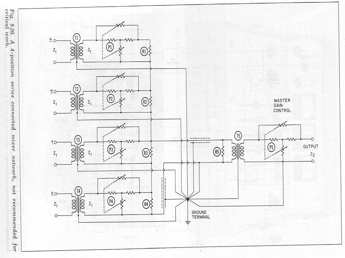
Series-mixing, 1931:
 

Attachments

  • Series-Mixing.gif
    Series-Mixing.gif
    21.4 KB · Views: 90
Back
Top