Vu/PPM meter

GroupDIY Audio Forum

Help Support GroupDIY Audio Forum:

This site may earn a commission from merchant affiliate links, including eBay, Amazon, and others.

Moses

Well-known member
Joined
Nov 27, 2008
Messages
188
Location
Edinburgh, Scotland
Hi!

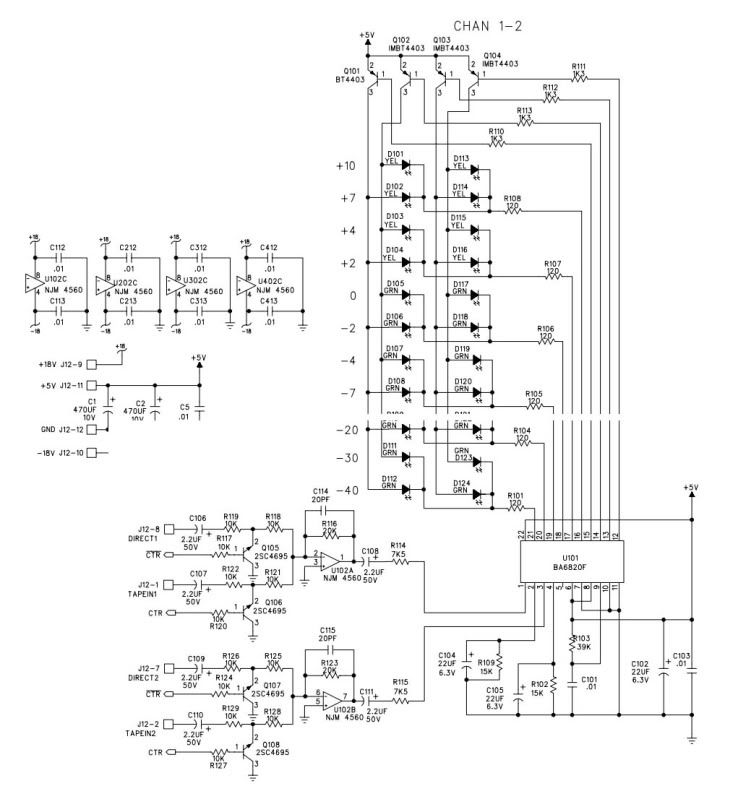
Im planning on putting together a VU/PPM meter, but I also want to include a crest factor meter in there.

I'm thinking that I can basically copy this Calrec UA8000 meter schematic, and connect a differentiator at the outputs of the VU Filter and PPM Peak detector circuits in order to create the crest factor reading.

However, Im a little confused as to how the Law CCT (bottom left) works, and what it does...

Any help is much appreciated!

Thanks,

Mo
 
That schematic was not clear enough for me to read when I blew it up big enough to see.

To make a direct reading "crest factor" meter, you want to compute the ratio between peak and average... We can do this with log math, by first converting the PPM (peak) and VU (average) into dB, then subtract the average from peak. That dB difference is the crest factor ratio. 

Back in the day, I used to perform log conversions using cheap transistor arrays but my old standby is obsolete now (CA3086). I guess the modern way would be to throw a pair of THAT corp RMS chips at this. Use a small cap on one to make the PPM response (4 mSec or so attack), and larger cap on the VU. The only thing I don't like about that is the Peak will have a fast release too, so the crest factor indication will be brief. Of course you could add a hold circuit with slower release to the PPM result or after the VU term is subtracted from PPM. 

I have never designed crest factor as a stand alone meter, but have made several simultaneous Peak/VU where the LED display is calibrated in equally spaced dB steps. By inspection you can read crest factor from the distance or space between the peak and VU value on the meter. For these meters I make the peak release time the same as the VU release time, so the crest factor is readable for a little time after the peak event has occurred, until the average level starts rising again from the next sound.

I like getting all three from a single display all the time, but maybe that's just me... 

I have designed microprocessor based meters with a mode selector switch so I could easily do the math inside the micro and provide a pure crest factor display but never had a customer request it.

JR

 
Hi John!

Thanks! That's essentially what's happening in the schematic: fullwave log rectifier, a voltage follower then split 2 ways (Sallen Key filter for VU averaging, and an AD full wave rectifier for Peak)... I was then planning on adding a differential amp to the two outputs, and another averaging circuit to 'see' the crest factor reading. So it sounds like Im on the right page! Phew!

Im kind of worried about the next block in the schematic, which is labelled Law cct... Im really confused by it, but I presume it somehow deals with timing constants? But I cant work out how it would do this, given that there don't seem to be any timing elements in the circuit (unless the 2nd opamp is acting as a gyrator with a route through earth?)... Much head scratching!

I've uploaded the full schematic (thanks to Gyraf!), because it seems to blow up better than that snapshot! We're in the topleft corner... http://bonningtonlanestudios.com/thelabdiy

Thanks,

Mo

 
Moses said:
Im kind of worried about the next block in the schematic, which is labelled Law cct... Im really confused by it, but I presume it somehow deals with timing constants?
As the name implies, this cct converts the linear voltage from the rectifiers in log deviation, in accordance with british PPM usage; IIRC, it is a 7 tick scale, with 4dB between each tick. Also called a DC log converter.
 
OK, that "law" circuit is AKA a "diode break amplifier".. basically a multiple linear slope approximation of a nonlinear transfer function. The resistor dividers select when the different slopes are in the feedback path.

A diode break amp is not my first choice for how to do this but perhaps adequate for a low resolution display.

JR


Thanks Abbey and John! Not much information to be found about such things, but the concept seems simple(ish) enough...

More head scratching to be done!

Mo
 
JohnRoberts said:
These days it's easier to do such things with a $2 micro...

JR

hey,
have you got any simple examples?
i want to make a bridge for my belringer desk from scratch, i finally have the schem, its the same as the mackies 8buss. it doesn't have to be complicated or a critical/huge scale.
maybe even just 5 or 6 led per channel?


meter.jpg


apologies for the hijack, i can post a new topic but thought it was kinda related :)
 
kepeb said:
JohnRoberts said:
These days it's easier to do such things with a $2 micro...

JR

hey,
have you got any simple examples?

Not that I can publish a schematic for...

file.php

http://www.johnhroberts.com/Candy.wmv

The hardware is pretty simple... code may involve a little work, but this strikes me as a perfect example of something cheap micro's do very well.

JR

 
> my belringer desk from scratch, i finally have the schem

That BA6820F is a cute chip. Two 12-step channels, 24 LEDs via 10 pins, power-on mute, peak hold, internal rectifier but also apparently a direct input.

datasheet

Can you get a few?

littlediode.com "Available in Stock - Shipped in 5 Days"

tautec-electronics.de "in stock: 1900" "The minimum order value is 100 Euro! Shipping and handling are 10 Euro within Germany!"

Space-age LM3916 is still around, Future Electronics has 4000 today and 20000 coming. At a buck and a half it seems cheap for DIY. My recollection is that by the time you build rectifier and filter and wire all the LEDs, the whole day is shot.

If you have (or want to have) any programming skills, John is probably right. Instead of dinking with rectifiers and filters and logs and gating, drop a micro-brain on it. They are available with one or more 6-bit to 16-bit ADCs, get the samples and massage them in code. The great thing is that when you have "wired" one channel, another one or seven channels is just cut-n-paste, no solder no parts-shortages.

I still prefer mechanical meters. And with the near-zero cost of strong little analog ICs, the old problem of electrical sensitivity versus fragility versus COST may be cracked: use a clumsy but rugged contraption and beat it with LM386 etc.
 
The main thing about the BA6820F I would advise some care about is that it is multiplexing the LEDs 4x6 at a 4K clock. This shouldn't be a problem up in the meter bridge away from sensitive circuitry but switching LED current is not without noise, and 4k is right where our ears are pretty sensitive, so keep layouts tight and PS decoupling local and robust.

I suspect the oscillators can be synchronized to each other by tying all the OSC pins together (but mostly guessing), to minimize beating, while I'm not sure if that is even an advantage over letting the clocks roll spreading out the peak noise.

Curiously you could pretty much replicate this part with a soft microprocessor that has 10 digital output lines and a handful of input A/Ds... But writing code for even something this simple is too much work for a one-off..  I did mine because I wanted to make a meter that does different tricks and for production the micro was cost effective compared to analog. FWIW I used the more expensive individual latch lines (one per LED) approach to avoid the noise of multiplexing, because the meter in the picture above lives in the master section of a console. For a more distant or less critical application, you can save drive lines and money by multiplexing. In my tuner product I have 30+ LEDs and I multiplex them to save a couple dollars worth of drive circuitry. 

JR


well tbh i was thinking it would be much simpler with modern/ different design. this things a few years old now, with the price of those components i could probably buy another one for what it would cost to replicate that original meter, before i start thinking about other hardware/enclosure and time spent.
just a simple hardware meter that was anything more than a clip light would be good.

interesting about the noise tho.
this one has a separate housing for the meter and was available separately but the later mx9000 had it all built into one.

i've never done any programming and it sounds as tho even if i had... this would be a poor choice of project to use up that amount of time on. are there no such things as pre-programmed micros or a bog standard vu meter approach?

i've seen vu's on portable recorders, shop signs and even tshirts! they seem more amazing than they did before.
 
Indeed over my career I've seen an evolution in design, from cobbling together more complex functions using simple discrete components, to moving slightly higher up the food chain using opamps and comparators as components, to finally fully integrated assemblies. If there is a large enough market for a stable enough function this large scale integration makes economic sense.

The modern trend that I see eclipsing LSI in many applications is inexpensive (digital) microprocessors with multiple analog inputs, and analog outputs (PWM, DAC).  While programming these is not free, their ability to cover so much old school analog ground has already made them cost effective in many design applications.

I am an old analog dog, who has been turned to the dark(digital) side by this remarkable power and flexibility. 

I won't argue that learning how to program makes sense to design one meter circuit, but i predict if you develop that skill set, you will find other problems to nail with that magic hammer.

JR

 
A little further down on the food chain, this circuit is simpler than the Calrec one and drives a mechanical meter with the log conversion being done optically on the meter scale  ;)

vudriver-r1sch.jpg


The circuit is from Ethan Winer, published in REP some years ago. I added a separate scale factor adjustment for the peak reading function so you can set the peak mode to read "0 VU" at (for example) +18 dBu. I also rescaled some component values to allow the meter to read higher incoming levels (not shown).

It fits on a small circuit board:

vudriver-r1brd.jpg


I too like the old school mechanical meters. The peak reading function is useful for DAW metering. I don't really know how to use a crest factor meter so I don't miss that function...

Cheers,

Michael
 
Yup, that is a more popular FW rectifier. While it still must slew two diode drops through zero, so will suffer gain bandwidth issues at low level and HF. Of course 20 kHz at -40 dB is not an issue for mechanical meter display. 

Speaking of Ethan... here's his latest project  http://www.youtube.com/watch?v=k5GSxNtScdo  (a rant about CT stop lights).

JR
 
JohnRoberts said:
Speaking of Ethan... here's his latest project  http://www.youtube.com/watch?v=k5GSxNtScdo  (a rant about CT stop lights).

JR

Strangely compelling viewing - I can't believe I've just spent 14m32s watching a vid about traffic lights in a place I've never been
and shall almost certainly never go, Well done Ethan.
M
 
Hi MJK,

Thanks for the schematic! Gonna have a wee look at it tomo...

Sorry I've not been around, the thread hasn't been letting me reply... John, I was wondering if you could explain how the diode break amplifier works, or point me in the direction of some reading material? There doesn't seem to be too much information available.

Yeah, I might look at coding a picaxe up for this... Will a PWM output play nicely with a mechanical meter? Likelihood of shortneing the lifespan of the motor?

Thanks all!

Mo
 
Moses said:
Hi MJK,

Thanks for the schematic! Gonna have a wee look at it tomo...

Sorry I've not been around, the thread hasn't been letting me reply... John, I was wondering if you could explain how the diode break amplifier works, or point me in the direction of some reading material? There doesn't seem to be too much information available.

Diode break amps basically come in different forms, but use the diode conduction to shift resistor into or out of a feedback network,

A real simple example is an inverting opamp, with input and feedback resistors.  In addition to the first normal feedback resistor, add a second resistor with a diode in series in parallel with that. For output voltages less than one diode drop, the gain is rin/rfeedback, But for output voltages more than a diode drop the second resistor conducts and gain drops, Addional didoes and resistor in series or attached to dividers can make various slope approximations of transfer function. These are crude, and IIRC there were even sine wave generators based on a several slope approximation, but distortion wasn't very low.

Yeah, I might look at coding a picaxe up for this... Will a PWM output play nicely with a mechanical meter? Likelihood of shortneing the lifespan of the motor?

Thanks all!

Mo

Using a micro to drive a mechanical meter is clearly the wrong tool for the job... There isn't much bneefit to working in the digital domain, to output to a mechanical meter.

In fact you could run the PWM into the meter and it would probably integrate the PWM for you, but not worth the complexity IMO.

The micro IMO makes more sense for many segment LED or whatever displays.

JR
 
Back
Top