[quote author="AnalogPackrat"]If you look at a typical time domain representation of a signal, you can see that there are two axes of symmetry--time and magnitude
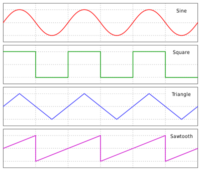
Now take our old friend the sawtooth wave. You have to invert its magnitude and mirror it in time (in half cycle pieces) to get it to match itself. It is not possible to do away with the mirroring. The sawtooth contains only even harmonics.[/quote]
thanks AP
I too wanted to look at the waveform and look at possible techniques from the synthesiser world
but I was trying to move away from continuous repetition of waveform (cycles) and look closer to the rate of change of the amplitude
I think the non-linearity we might want is continuos and without instant change
Wayne is right that this would be level dependant and initially I was thinking that would probably be the implementation of the SSL
which was the point of the thread ... but I'm happy to widen it and let it be something new and not a clone.
... even though I think it is very hard to do anything with a simple circuit and handful of the basic components that hasn't already been done before. The stomp box world hasn't had a new idea in my lifetime ... at least I don't think so. I'm sure you could patent a resistor and pass it off at a new circuit idea ... sorry ... pet peeve
AP
"
the saw tooth has only evens"
I thought both saw and reverse saw contained all integer harmonics ??
they sound the same anyway
but can help hightlight a circuit that is asymmetrically clips ... sory I'm back on clip and soft clip again
perhaps I'm not getting the significance of the mirror in half cycle pieces.
...
wouldn't that make it more like a triangle wave ... lots of odd ?
Whatever the process might turn out to be it probably is working directly and in sync with the waveform itself so Wayne's cool circuit leaves me thinking envelope because of the RMS detector rather than waveform.
just for fun
the above doesn't show a crossover distortion ... or step thing
but then as Wayne pointed out above (earlier page)
we probably don't want that
not having seen or heard the SSL product
but a couple of questions before I get into more trouble
how many controls does it have ?
odd - even - on - off ?
mix - wet/dry ?
is it level dependant ?
etc
And I can hear the difference in some instruments when they're "upside down" at the ear. Shoot me if you think I'm wrong.
once they have passed through a circuit that introduced distortion ?
or simply straight out of the recorder as pos or neg polarity ?
this was very much the content of that thread I started ... long ago in the wayback machine
it was also the subject of one of the Group DIY updates.