OK, I can't help but step in here! Back in 2005, I started asking "what's the origin of the voltage that must exist to push current around a so-called "ground loop?" I asked my smartest colleagues and never got an answer that was consistent with real-world measurements. But I had a hunch and did some table-top experiments to confirm that my theory was right. In 2010, I designed a controlled experiment and collaborated with a young EE friend with math skills fresh from college to predict my results using Maxwell's equations. I published the results in a 2011 AES paper "Ground Loops: the Rest of the Story". I've attached a couple of PowerPoint slides I use in my seminars to explain where this voltage source is. It's not "just there" as most people assume. The paper explains how the geometry of the current-carrying conductors in the premises wiring magnetically induces EMI voltage into the ground/PE conductor. And, because the voltage is proportional to the rate-of-change of the current (Faraday's law) in the load conductors, the voltages get higher with frequency. This also explains why we usually hear "buzz" rather than "hum" - and why phase-control light dimmers are such a nightmarish problem for noise. It also shows why tightly twisting the current-carrying conductors before they're pulled into conduit can reduce the inducted voltage by 1000:1 (60 dB) or more. This twisted L-N branch circuit technique has been installed in several large venues including the Disney concert hall in Los Angeles and the Bing auditorium at Stanford University. The folks who subsequently installed sound systems in these venues were amazed that they had absolutely no system noise right from the start. Anyone interested in the AES paper can drop me a line at [email protected] or, if you're an AES member, you can download it for free at the www.aes.org.
You are using an out of date browser. It may not display this or other websites correctly.
You should upgrade or use an alternative browser.
You should upgrade or use an alternative browser.
Xlr grounding
- Thread starter EmilFrid
- Start date


Help Support GroupDIY Audio Forum:
This site may earn a commission from merchant affiliate
links, including eBay, Amazon, and others.
Thanks again Bill ,
So the very same technique used in microphone cables to reduce unwanted noise ingress ie a twisted pair also helps mains installations better cancel noise emissions from the cables ,that makes sense now I think about it .
Just at the moment Im looking over the mains system in a property Im hoping to buy ,
I had both the utillity company and an electrician check things and although quite old its still upto the job. I will have to replace old style fuses with modern electronic breakers and a few old sockets that have seen better days , otherwise its perfectly functional .
I asked the electrician about using the standard industrial steel tubing, metal sockets ,switches and back boxes and he winced , said it was way above and beyond whats required .
I didnt bother getting into the convo about mains borne interference with him .
The code for electical wiring has changed here in recent times , the old grey double insulated wire (live ground neutral)has been replaced with one with a white outer jacket , lighting circuits are now required to have a ground ,where before two single cores of double insulated wire was good enough
Is it worth the extra effort to run twisted pairs inside steel conduit in a domestic situation ?
In any case I would like to take a look at the AES paper on the subject , so I'll send you an email tomorrow with my username here as the reference .
Sorry for not replying until now. Very interesting discussion that spawned out of this. Didn't expect so many insightful replies actually. The more I think about it, the more sense it makes to just go with a couple xlr patch panels for mics. I could have xlr panels drilled into the wall and then the console patchbays taking care of everything else. Seems like the most durable, sonically sound (pun intended) and versatile alternative.
Back in my days in pro studio work , the good engineers would insist that the main vocal mic at very least didnt go anywhere near a patch bay , now what we term 'ground' is a more hostile sonic environment than it ever was back then .
I have absolutely never connected pin 1 of XLR connectors together at a remote location (stage box, etc).
Remote location setups are a different consideration because of the possibility of varying potentials on the earth conductor.
The responses were specifically regarding the original post which described two recording rooms in the same building, only a (relatively) small distance from the console in the control room, with only the console as an active device providing phantom power, and the devices on the other ends being microphones (or presumably occasionally some other device you want to record, such as guitar processor, synth, etc.).
EmilFrid will not have to have nearly as complicated a setup as when e.g. sending microphones to FOH and stage monitor console at opposite ends of a stadium, and then also to remote recording truck in the street, where all are possibly running from different power feeds.
moamps
Well-known member
...
The responses were specifically regarding the original post which described two recording rooms in the same building, only a (relatively) small distance from the console in the control room, with only the console as an active device providing phantom power, and the devices on the other ends being microphones (or presumably occasionally some other device you want to record, such as guitar processor, synth, etc.)...
I agree with you that there probably won't be any problems in that example, but you never know. Imagine a small mixer in room A with a 2 ch multicore and a large mixer in room B with 24 channels and all pins 1 of XLRs from both mixers are connected together in, say, the connection box of the live room. If, for example, mixer A is used and it provides phantom voltage for 2 microphones in the live room, there is a high probability that phantom current will flow through the shields of the multicore of room B (less resistance) and the grounding of the power cables of mixers. By connecting the pins 1 of XLRs in the connection box, a large grounding loop was created, which is unnecessary and potentially dangerous.
EmilFrid will not have to have nearly as complicated a setup as when e.g. sending microphones to FOH and stage monitor console at opposite ends of a stadium, and then also to remote recording truck in the street, where all are possibly running from different power feeds.
In that case I would suggest a rack full of BSS MSR 604 splitters.
")
but you never know. Imagine a small mixer in room A with a 2 ch multicore and a large mixer in room B with 24 channels and all pins 1 of XLRs from both mixers are connected together
But we do know, the original poster specifically said there was one control room with one mixer and two live rooms with microphones.
I'm not going to try to solve every potential unasked question every time one person asks one specific question.
moamps
Well-known member
You're right, my apologies. I unintentionally wrote the example I used to explain why it's not a good idea to connect all studio-side XLR shields together to a forum member who asked me about it offline. I should be careful what I write around midnight.But we do know, the original poster specifically said there was one control room with one mixer and two live rooms with microphones.
Newmarket
Well-known member
Patchbays of any discription on low level signals eat away at noise floor , fact
Not certain what you mean there ? Intermittent connections ? - that's a fault and not really "noise floor". Or discontinuity of screening allowing external noise interference ?
Ground currents , more than anything , as Mo said patchbays tend to create large loops ,
flakey foil and wire screens , phantom power , tube mic supplies opperated from different mains outlets in another part of the building etc , the list goes on an on really , its best to avoid or minimise loops because they act like aerials .
flakey foil and wire screens , phantom power , tube mic supplies opperated from different mains outlets in another part of the building etc , the list goes on an on really , its best to avoid or minimise loops because they act like aerials .
Newmarket
Well-known member
Ground currents , more than anything , as Mo said patchbays tend to create large loops ,
flakey foil and wire screens , phantom power , tube mic supplies opperated from different mains outlets in another part of the building etc , the list goes on an on really , its best to avoid or minimise loops because they act like aerials .
Okay. But those are implementation issues wrt Ground/ Screen/ Pin 1 and Shell connection. Rather than intrinsic patchbay issues.
Agree re foil/drainwire screen issues.
I've had particular emi related battles over that in a non-audio scenario.
Audio1Man
Well-known member
Electricians need to know the electrical code to perform their work. They are not Engineers / Scientists. They commonly use plastic boxes, Romex, wire push in outlets, maybe alum flex or BX.
If you need to have a clean noiseless area you need to build it with care.
To reduce noise components of EMF (both magnetic and electrical fields) the use of steel (Not ALUM) for boxes, flex, EMT, BX, green ground wire, isolated outlets, twisted H-L, (No common/shared neutral’s), ground loops and spacing are strange to many of electricians.
If your electricians tell you don’t need it, hire one that does.
Bill & I are Engineers / Scientists and we look deeply into resolving problems.
SOME SPECIAL TOOLS FOR THE TRADE:
- SMALL PLASTIC BATTERY AM RADIO (cheap TF2). Mine has a RCA cable + RCA to Dual Banana that is connected to the speaker, that can be connected to a DVM
- TriField EMF meter TF2
- Polarity / GFI tester
- U GROUND ADAPTER used only for quick debug tests. NEVER USED TO RESOLVE THE NOISE ISSUE.
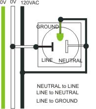
This is an old rant of mine but cheap 3 lamp outlet testers can be tricked by RPBG (reverse polarity bootleg ground) and will indicate all good with this dangerous wiring mistake. The good news is that RPBG is not common with modern properly wired buildings, but this can and has caused deaths because the energized safety ground energizes the chassis et al.SOME SPECIAL TOOLS FOR THE TRADE:
Duke
- SMALL PLASTIC BATTERY AM RADIO (cheap TF2). Mine has a RCA cable + RCA to Dual Banana that is connected to the speaker, that can be connected to a DVM
- TriField EMF meter TF2
- Polarity / GFI tester
- U GROUND ADAPTER used only for quick debug tests. NEVER USED TO RESOLVE THE NOISE ISSUE.
An old school trick to probe for hot leads is to use a simple neon lamp probe. Grasp one lead while probing with the other. The human body will provide a vague ground reference (enough to light a neon bulb). Another variant on this is grab one lead of a VOM in a high AC volts range while probing with the other lead. Probed energized leads will generally register 60VAC in US outlets. Caution while the typical neon lamp tester is current limited, a VOM on the wrong scale could expose you to dangerous voltage/current.
For TMI OD-1
JR
Similar threads
- Replies
- 2
- Views
- 218
- Replies
- 0
- Views
- 245
- Replies
- 5
- Views
- 968