Andriejus
Well-known member
Hi All,
So here are some pictures of some design changes in the kit that you will receive:
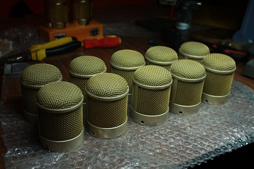
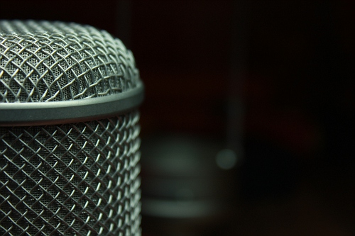
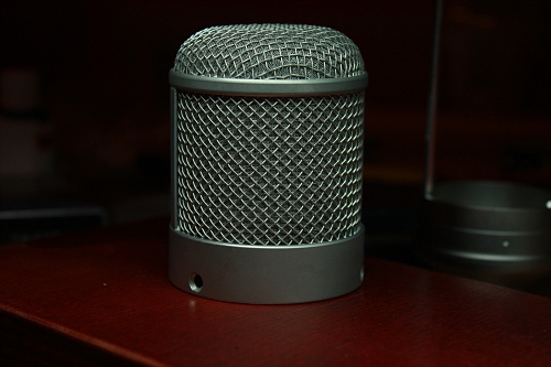
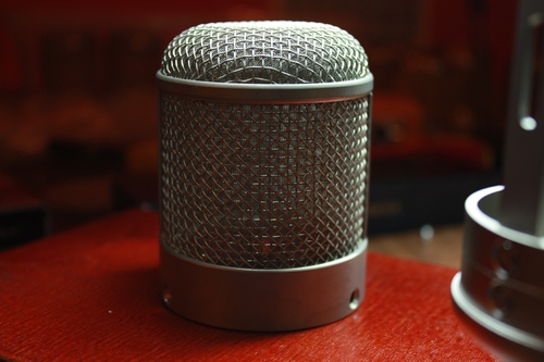
1. Bigger radiuses on the edges of upper headbasket ring:
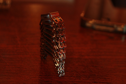
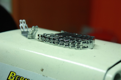
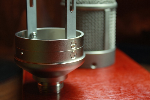
2. Winged fixing ring added to prevent the female connector from loosening and spinning around:
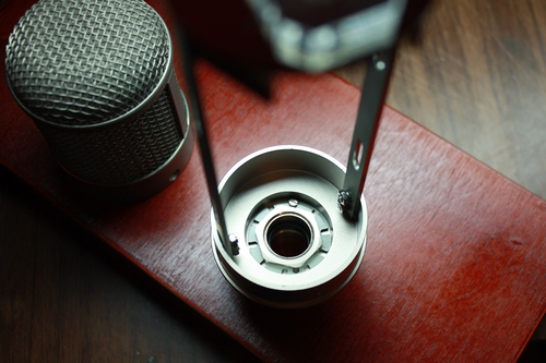
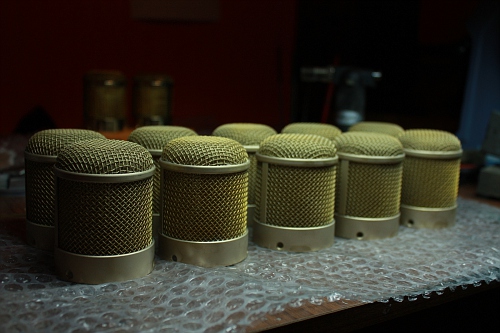
3. End bell now has better plating and lathe cut for more accurate positioning:
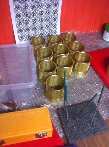
And here are some little puppies ready for soldering...
By the way - I had some questions about the surface plating which from the first time may seem too sensitive to finger prints. Do not worry, this will become resistant to finger prints in few weeks. It just needs some time for oxidation. Also some may notice marks left from wooden box holders. This is the same oxidation.
All fingerprints and other marks during oxidation process can be easily removed with dry and soft cloth.
And also do not forget to wear rubber gloves while assembling the mic, this will help to avoid further cleaning.
Also DO NOT OVER TIGHT THE SCREWS OF HEADBASKET. Threads are strong enough to hold the pressure as they are taped in stainless steel, however tight the screws until it becomes concentric and touches the chamfered surface of a headbasket - simply until it is enough.
Kind regards,
Andrew
So here are some pictures of some design changes in the kit that you will receive:
1. Bigger radiuses on the edges of upper headbasket ring:
2. Winged fixing ring added to prevent the female connector from loosening and spinning around:
3. End bell now has better plating and lathe cut for more accurate positioning:
And here are some little puppies ready for soldering...
By the way - I had some questions about the surface plating which from the first time may seem too sensitive to finger prints. Do not worry, this will become resistant to finger prints in few weeks. It just needs some time for oxidation. Also some may notice marks left from wooden box holders. This is the same oxidation.
All fingerprints and other marks during oxidation process can be easily removed with dry and soft cloth.
And also do not forget to wear rubber gloves while assembling the mic, this will help to avoid further cleaning.
Also DO NOT OVER TIGHT THE SCREWS OF HEADBASKET. Threads are strong enough to hold the pressure as they are taped in stainless steel, however tight the screws until it becomes concentric and touches the chamfered surface of a headbasket - simply until it is enough.
Kind regards,
Andrew
")