[silent:arts]
Well-known member
I started to calibrate a F760 at work two years ago ...
Seamed to be an easy job, since I found the calibration manual (in german) at work too.
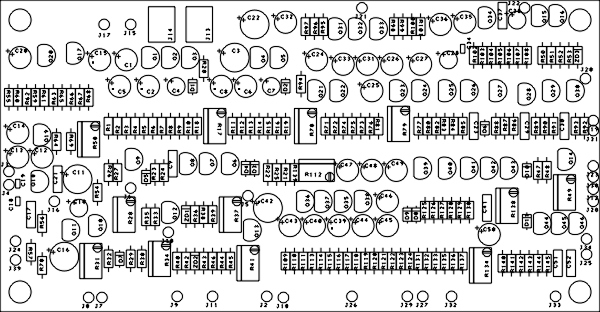
started to tweak the trim pots, realized too late the PCB has 3 more trimpots than the drawings / descriptions ???
Seamed to be an easy job, since I found the calibration manual (in german) at work too.
started to tweak the trim pots, realized too late the PCB has 3 more trimpots than the drawings / descriptions ???