FET "Grinder"

GroupDIY Audio Forum

Help Support GroupDIY Audio Forum:

This site may earn a commission from merchant affiliate links, including eBay, Amazon, and others.
You can check the PSU feed by disconnecting it and measuring the outputs from the PSU board - at least that would eliminate a possible problem.

Sometimes people short the wires on lacquered transformer wires, which means they will have  hard time getting a connection. Thats usually the cause of fallouts.

Did you check the different trimmer values when placing them?

Gustav


Rocinante said:
tata said:
"Product Code: SYMKIT
Availability: Coming soon"

please Gustav, how soon?

I was just gonna post the same thing.

tata said:
"Product Code: SYMKIT
Availability: Coming soon"

please Gustav, how soon?

I could put a "semi-finished" kit up for sale now, but...

1. I have pots (only for a dozen units or so). They are 4mm and they take a little work to fit onto the PCB. I ordered a batch of alpha pots for the project a few weeks ago, and expected delivery was 8-12 weeks. I HOPE they are the correct ones, since the ordering procedure is somewhat confusing to me :)

2. I only have a dozen of the original, dual JFETs, and I feel like there should be a recommended replacement for a kit.

I received a bag of them from China recently, but they turned out to be fakes. The pinout is correct, but I am getting slightly different values with the diode tester, and they look radically different.

They may turn out to be fine and sound great, but I may need to find a replacement or match two single Jfets for it. I will start testing the ones I have and alternative replacements when its back on my bench (its currently out of town for a video-shoot), and I also have a possible lead on another batch of originals, which, of course, would be the easiest solution :)

Please post in the thread I made for the specific project - and don't be afraid of sourcing the parts yourself. The 4mm pots can be found at Reichelt.de, and there are many alternative, available FETs you could try out. Just socket them and swap them around :) The rest is all standard stuff..

Gustav


Gustav said:
You can check the PSU feed by disconnecting it and measuring the outputs from the PSU board - at least that would eliminate a possible problem.

Sometimes people short the wires on lacquered transformer wires, which means they will have  hard time getting a connection. Thats usually the cause of fallouts.

Did you check the different trimmer values when placing them?

Gustav

Ok so I check it today by changing the FET and the comp is working for 20mn, when i came back to calibrate it, i put power on and the same problem, no bass on the sound.
So maybe something happen?But impossible for me to know why...
I'm a little bit lost
 
Mazieresantoine said:
Gustav said:
You can check the PSU feed by disconnecting it and measuring the outputs from the PSU board - at least that would eliminate a possible problem.

Sometimes people short the wires on lacquered transformer wires, which means they will have  hard time getting a connection. Thats usually the cause of fallouts.

Did you check the different trimmer values when placing them?

Gustav

Ok so I check it today by changing the FET and the comp is working for 20mn, when i came back to calibrate it, i put power on and the same problem, no bass on the sound.
So maybe something happen?But impossible for me to know why...
I'm a little bit lost

1. Check the main 1176 thread as suggested by Jakob.

2. Start with the basics. Voltages good on the PSU unconnected? Voltages good in the circuit?

Link to schematic with voltages pencilled in - http://gyraf.dk/gy_pd/1176/1176sch.gif

Gustav
 
Thanks for your help,

I will start again to check everything.
What i know is that voltage is good on the PSU.

Just a non-subject thing, i have finished a GSSL from your site, with 2 S/C and Turbo mod and it's working so good!thanks for this one!
I sent you a picture when my frontpanel is done
 
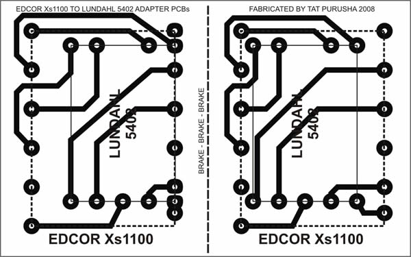
Okay...  So I have Gustav's "second rev." pcb; the "Phat Phet" and want to take the Edcor xs1100 route instead of the Lundahl 5402 for the output xfmr?  Do I need an adapter board like the one Don Audio sells or the one below or can these be wired directly?  If so, anyone know of a link to where the wiring scheme is?
XzZZMqh.jpg


  Sorry for the noobie question.
 
Rocinante said:
anyone know of a link to where the wiring scheme is?
XzZZMqh.jpg

If I were in doubt, I would use the board you just posted for reference when/if wiring :p ;)

Gustav

 
Hello, I finished a dual fet compressor and so far both sound great and works as a spected, still need to calibrate the meters, but I have a small issue with the noise on the right channel, not too much but compare it to the left is not the same, turning the input knob 3/4 to the right on the right channel noise appears on my analyzer -70dbs, I checked cables, connections, switched Ic's but the noise still there, any one have an Idea where to start looking?

Thanks for your help
 

Attachments

  • image.jpg
    image.jpg
    1,001 KB · Views: 89
jicama said:
Hello, I finished a dual fet compressor and so far both sound great and works as a spected, still need to calibrate the meters, but I have a small issue with the noise on the right channel, not too much but compare it to the left is not the same, turning the input knob 3/4 to the right on the right channel noise appears on my analyzer -70dbs, I checked cables, connections, switched Ic's but the noise still there, any one have an Idea where to start looking?

Thanks for your help

looking at your pict, may I suggest to start with a clean wiring ?
All this cable crossing each other in an absolute chaotic way....man  :-X
and i'm not talking about main trafo and regulator layout, is that modulation I/O cable passing over the regulator and close to trafo?
Zam
 
jicama said:
Hello, I finished a dual fet compressor and so far both sound great and works as a spected, still need to calibrate the meters, but I have a small issue with the noise on the right channel, not too much but compare it to the left is not the same, turning the input knob 3/4 to the right on the right channel noise appears on my analyzer -70dbs, I checked cables, connections, switched Ic's but the noise still there, any one have an Idea where to start looking?

Thanks for your help
What kind of noise are you hearing,hum and overtones?
I think member zamproject is right,this is really an example how it should not be done!
Seriously,I even wonder that you only have "..... A small issue..."!
So here it goes:You should lift nearly all wiring and do it once more.
The transformer is mounted correct so far.
Try to run all your audio wires so they don't cross any parts in the psu,especially not the transformer.
Also twist(!!!) wire pairs like the ones going from and to the XLRs as well as the others!
Try to run them short to the front panel etc.,in general:Make them look nice and clean.
You will be amazed how good your compressor will work after you're done.  ::)

Happy "cleaning",

best regards,

Udo.
 
kante1603 said:
jicama said:
Hello, I finished a dual fet compressor and so far both sound great and works as a spected, still need to calibrate the meters, but I have a small issue with the noise on the right channel, not too much but compare it to the left is not the same, turning the input knob 3/4 to the right on the right channel noise appears on my analyzer -70dbs, I checked cables, connections, switched Ic's but the noise still there, any one have an Idea where to start looking?

Thanks for your help
What kind of noise are you hearing,hum and overtones?
I think member zamproject is right,this is really an example how it should not be done!
Seriously,I even wonder that you only have "..... A small issue..."!
So here it goes:You should lift nearly all wiring and do it once more.
The transformer is mounted correct so far.
Try to run all your audio wires so they don't cross any parts in the psu,especially not the transformer.
Also twist(!!!) wire pairs like the ones going from and to the XLRs as well as the others!
Try to run them short to the front panel etc.,in general:Make them look nice and clean.
You will be amazed how good your compressor will work after you're done.  ::)

Happy "cleaning",

best regards,

Udo.

Jejejej!!

Thanks for the advise!!
I'll post back when I clean this jungle!

Cheers
 
jicama said:
Jejejej!!

Thanks for the advise!!
I'll post back when I clean this jungle!

Cheers
Yep,and post a front pic too,we all want to see how it looks (I bet....).
And don't be ashamed,we all did some weird things when we started ;)

Udo.
 
Jicama

Can I also suggest as you have to redone the whole wiring to made some change in the layout.

rotate 90° both comp card and translate to the left, max as possible (view from front) hoping your case have enough depth.
rotate 90° your PSU card and translate to the right,
By this you easy resolve audio cable (from card to xlr connector) over PSU
also take care of the main switch cable I see black one (switch to trafo ?) like touching opamp and lundhal  :-\

best
Zam
 
zamproject said:
Jicama

Can I also suggest as you have to redone the whole wiring to made some change in the layout.

rotate 90° both comp card and translate to the left, max as possible (view from front) hoping your case have enough depth.
rotate 90° your PSU card and translate to the right,
By this you easy resolve audio cable (from card to xlr connector) over PSU
also take care of the main switch cable I see black one (switch to trafo ?) like touching opamp and lundhal  :-\

best
Zam

Ok gentleman's  here is so far the cleaning, I haven't test it yet, I'll do it when I get home and post back the results, here is a pic as well from the frontal ; )
 

Attachments

  • image.jpg
    image.jpg
    953.6 KB · Views: 64

Latest posts

Back
Top