You are using an out of date browser. It may not display this or other websites correctly.
You should upgrade or use an alternative browser.
You should upgrade or use an alternative browser.
GSSL HELP THREAD!!!
- Thread starter hairyandy
- Start date


Help Support GroupDIY Audio Forum:
This site may earn a commission from merchant affiliate
links, including eBay, Amazon, and others.
Hello Guys.
I need help with this unit rev12
please listen to this audio clip.
When i switch off the unit i get this sound. :
http://www27.zippyshare.com/v/pnrdD4T6/file.html
i did a triple check on every component- and are okay.
all resistors are ok , compared to the layout. and measured before mounting.
22uf radial caps idem
100 uf radial caps idem
10pf , 33 pf , 100 pf , and 22pf idem.
0,1uf also measured before mounting , and all them are on its place.
in the past. i had the same problem with a unit i built , the problem was that i put on the o.1uf caps // 1uf wima caps.
and i solved the problem with the 0.1uf wimp caps ( the correct ones)
the unit also was working fine like this one .
now i hear the same noise on this unit . but everything is on its place.
is like a capacitor discharge ? : /
before swap all 0.1uf caps..would be very appreciated your help , or a suggestion of where i can find the problem.
the unit works fine..and perfect !!
Other thing i noticed is only happens if the threshold pot is at the end of counterclockwise( in fact to be exact , starts at 3/4 of the total amount of threshold to the end.) and without processing any signal.
if you switch off the unit while compressing a signal. that not happens never.
Weird !
I think im the only one with this problem ( in fact is no t a problem but i prefer to know what is going on there") )
)
thanks in advance!!
I need help with this unit rev12
please listen to this audio clip.
When i switch off the unit i get this sound. :
http://www27.zippyshare.com/v/pnrdD4T6/file.html
i did a triple check on every component- and are okay.
all resistors are ok , compared to the layout. and measured before mounting.
22uf radial caps idem
100 uf radial caps idem
10pf , 33 pf , 100 pf , and 22pf idem.
0,1uf also measured before mounting , and all them are on its place.
in the past. i had the same problem with a unit i built , the problem was that i put on the o.1uf caps // 1uf wima caps.
and i solved the problem with the 0.1uf wimp caps ( the correct ones)
the unit also was working fine like this one .
now i hear the same noise on this unit . but everything is on its place.
is like a capacitor discharge ? : /
before swap all 0.1uf caps..would be very appreciated your help , or a suggestion of where i can find the problem.
the unit works fine..and perfect !!
Other thing i noticed is only happens if the threshold pot is at the end of counterclockwise( in fact to be exact , starts at 3/4 of the total amount of threshold to the end.) and without processing any signal.
if you switch off the unit while compressing a signal. that not happens never.
Weird !
I think im the only one with this problem ( in fact is no t a problem but i prefer to know what is going on there
) thanks in advance!!
my voltages are:
power supply ac 16,50v ( the trafo is a 2x15v)
after bridge rectifier dc +21v // -21v /// before bridge AC 16.43v
rails: +14.60/ -14.9v
7915 -14.9 v
7815 - 14.5v
7812 11,9v
tl074: pin 4 , 11.88v // pin 11 / -11.95v
tl072: pin4 . -11,94v /// pin8 , 11,88v
input :
5534 : pin 1 , 12,1v // pin 4 , -14,92v //pin5, -0,61v // pin7 , 14,56v // pin 8 ,12,10v
both same values , almost identical
55332: pin 4 , -14,93v /// pin 8 , 14,42v
both same values , almost identical.
vca section:
5534 pin1 , 12,18v // pin4 -14,92v /// pin5 -0.74v /// pint 7 , 14,59v // pin8 12,12v
both same values almost identical
SIDE CHAIN VCA that 2180b : pin 5, -2,82v // pin 7 11,88v //
vca left that 2180b : pin5 , -2,87v // pin 7 , 14,55v
both almost identical values.
Is there something wrong?
Also i Noticed that with HPF // ON , threshold at counterclockwise , AND COMPRESSOR OFF,
the sound is bit distorted, is more noticeable on low freqs.
, but disappears as soon you activate de compression .
this happens only with threshold at counterclockwise ,
Any suggestion ?
cray said:Is there something wrong?
Since you have a working unit, you could open the lid and compare the two.
Gustav
Gustav. everything is the same values on both units.
awesome
may be a difference of 0.10 / 0.20 v measuring.. but almost identical
awesome
may be a difference of 0.10 / 0.20 v measuring.. but almost identical
Gustav said:cray said:Is there something wrong?
Since you have a working unit, you could open the lid and compare the two.
Gustav
FIXED !!
haha.. don't buy 7915 made in MOROCCO.
Replaced for a new one made in Malasia.
ST 7915
both works fine. but the one from morocco makes that noise when I turn off the unit.
Could be the same on any brand. just bad luck i think
best!
C.
haha.. don't buy 7915 made in MOROCCO.
Replaced for a new one made in Malasia.
ST 7915
both works fine. but the one from morocco makes that noise when I turn off the unit.
Could be the same on any brand. just bad luck i think
best!
C.
Gustav said:cray said:Is there something wrong?
Since you have a working unit, you could open the lid and compare the two.
Gustav
JacobAskim
New member
- Joined
- Apr 28, 2016
- Messages
- 1
Hi!
I am a bit of a newbie in the DIY-world. So maybe these are really silly questions. But here goes nothing:
I am in the process of getting all the components for the GSSL Clone. I have managed to find everything except two things. I hope someone in here can help me with these two questions:
1)
In Jakob's(Gyraf) component list there is a bulletin called "16pcs CRIMP TERMINAL for PCB connectors". What is a CRIMP TERMINAL for PCB connectors? I have tried to google it, but I can't seem to find out specifically what I am supposed to buy. And I can't find anything with this name on Banzaimusic.com or Mouser.dk.
2)
I can't find 1N4148 small signal diode, with the specs. : 80V-0.1A.
However, at Banzaimusic.com I can find a 1N4148 Silicon Universal Diode 75V 150mA DO35.
So how is it? Can I use a diode that is 0.5V short or does it have to be exact, or can it be above for that matter?
I have found almost all my components on banzaimusic.com and I would like to buy this last part there too, so I don't have to order home 6 diodes + Shipping from some other webside.
I hope you can help me!
Jacob
Jacob,
If you put your location in your profile, it's much easier to help with things like sourcing.
1) these are the "inserts" for the female part of the connectors - they go onto the cables. I know them as "PSK 254 contacts" e.g.: http://www.reichelt.com/PSK-KONTAKTE/3/index.html?&ACTION=3&LA=446&ARTICLE=14861&artnr=PSK-KONTAKTE
2) Any 1N4148 or similar will do.
Jakob E.
Hi all,
I just finished a gssl bus comp, and iafter some tests i have this problem :
Without the sidechain board, the signal is well compressed. But since i wired the super sidechain board, the threshold is completely insufficuent to compress the signal..the vu meter just moves a little bit, even with threshold completely counter clockwise and i have to send a very loud signal. The documentation for the SC board says in "off" position, the signal is compressed as before, but it is not the case for me..
Did somebody have the same problem ?
I assume the main pcb is ok, and the wiring is ok too, i check resistors and ceramic caps of super sidechain board, good values...if you have any idea please share it.
Can i change the threshold pot with a higher resistance or will i lose something in term of quality ?
Thanks
UPDATE: problem solved, the IC1 of SSC board was not in good condition.
Potato Cakes
Well-known member
**Long Post Alert**
After my first GSSL (my first DIY rack unit) sat on the shelf when I couldn't seem to troubleshoot it, I came back to it after successfully building a bunch of other units, including another GSSL, and now it is finally useable. I wanted to share some thoughts for the guys just starting out in the DIY world and hopefully it will be helpful for avoiding the problems I brought upon myself when working on this project.
Someone earlier on this thread said to make a working unit first before trying to alterations. This is the golden DIY rule (or at least one of them) when one starts their first project. I had succumbed to the temptation of doing all the mods at one time for my first GSSL. I did the Cavendish, Super Side Chain, and a parallel mix circuit. So after wiring everything and barely cramming all the boards into a single space chassis, I fired it up and it did not pass audio. Now the trouble is where in this mess is the problem. I pulled everything out and unsoldered the other add on PCBs. I found some ICs incorrectly oriented and was able to get audio to pass, but no compression. I swapped out the ICs controlling the compression circuit. When that didn't work I saw on this thread someone had a solder joint that was causing his GSSL to not compress. I combed over my soldering and when I couldn't find anything, I wound up removing all the solder and then resoldering all the components. Still nothing. Did the same process to the ratio PCB without any results. Finally I saw that I had one of the cables swapped between the main and ratio PCBs and then it started working. Mind you several days worth of staring at PCBs and reading and trying out different solutions had occurred during each phase of troubleshooting.
Then I had all these add ons that I didn't want to go to waste, so I decided to put them back in. At first was the Super Side Chain. Wired it back in and it was working as it should. I put the parallel mix circuit in and I believe that it was fine as well. When I put the Cavendish in I was getting noise that changed with the position of the wet/dry mix pot. I also noticed that when the I mixed the wet and dry signals, I was getting cancellation. To confirm this I took a 2623-1 that I had laying around and wired it for reverse polarity on the wet signal and saw that the two inputs to the parallel PCB were now summing. I rewired the wet signal to the In - of the return DOA on the Cavendish to prevent canceling, but I still could not completely get rid of the buzz and hum. As you can see in the picture, I pulled the parallel PCB out and placed it outside the chassis away from the transformer, but I could not fix the problem. I pulled that board out of the GSSL and the noise was gone. I have not been able to incorporate both the Cavendish and the parallel mix board without causing some sort of grounding problem. I also found one side was distorting when there was low end in the program material, and it turned out to be a bad DOA that I had built a long time ago.
Now it's working and I'm going to slam the lid on it and never again think about the mess of wiring that was created from redoing all the connections many times. I do plan on building yet a third one for live use and utilizing the parallel mix PCB as I find this feature useful keeping things together without completely smashing everything and removing dynamics from a live show. This was my original intention, but I wouldn't take the one I just fixed on the road without completely gutting it and redoing the wiring, and I wanted to be finished with it and move on.
So here are my suggestions for people new to all this who plan on building a GSSL (or any of the amazing projects made by the amazing people on this forum). As stated before, build a working unit first. Whilst doing so, go slow, double check component values and which way they need to be placed, and use very fine solder to prevent accidental bridges. Believe me, it is very frustrating and somewhat emasculating to spend long periods of time putting one of these projects together to have it not work. If you are having issues, it is highly likely you made an error with component placement/orientation, wiring, or just a faulty solder joint/bridge. It is rare nowadays you will have a bad component, but not impossible. I'm not saying anything that hasn't been said many times all over this forum, but it seems that with a fair amount of frequency the culprit of people's trouble with their builds turns out to be one of the issues listed above. If you have a successful build and what to add something to it, I would recommend the turbo mod to make it behave more like an original SSL compressor, which is why we all wanted to build one of these in the first place. Cavendish is cool if you want to mess around with a bunch of DOA combinations and see how it affects the sound. And again, the parallel mix is great if you plan to use this for live. I haven't done any comparisons with the Thrust mode on the Super Side Chain to see how much different it is, but I believe that if you do the turbo mod you will have less need for a HPF for the compression side chain.
I hope this helps!
Thanks!
Paul
Attachments

Hello GDIY, this is my first post here, but ive been following the thread closely during my GSSL build process.
First of all i would like to express my gratitude to mr Jacob and mr Gustav for providing all information anyone on earth would need. Thank you very much!
Getting to the point:
Everything seems to be working as it should from first power on. I actually compressed some material before even monitoring any values and the results were great.
Today i visited a very skilled friend-tech, who has made the build several years before[rev 9 with 2181VCA mono moded, 100% working] and he mentioned to me that i had very weak compression. So we hooked both units to smaart with pink noiz and observed that his circuit had around 24 db of compression max, while mine had a mere 8-10 db of max compression full on.((
We counted the 5534's and there were no flaws. (I cant provide the exact values, as i have no access to metering tools yet.)
No problems with audio, but his unit could literally brick-wall whatever we run through it, while mine was "obviously compressing".
So, my first thoughts were:
-A possible problem at the 47K's Sidechain input sum resistors. I will check it, but i dont think so..
-The 47Ks for reduced threshold sensitivity, but we indicated that -30 db of thresh was at 2 o'clock[0db fully clockwise]. So im wandering if its healthy to consider it "too senseless"...
-Maybe the Bypass Switch is too big and degrades the signal from vca's control, but i thnk that this would have caused timing problems. Anyway i counted the resistance when i got it [mains switch] and was almost 0 to my cheap meter.
-Lastly my mind got to the 3K9s at pin 5, which doesnt seem to be the point, as it is related to the power of the VCA...
My problem is that i cant adress the cause by searching in the thread, as its too complicated to write and results are irrelevant
I believe someone with experience on the revisions can pinpoint a direction or a search term for my situation.
Thank you all!
Regards
First of all i would like to express my gratitude to mr Jacob and mr Gustav for providing all information anyone on earth would need. Thank you very much!
Getting to the point:
Everything seems to be working as it should from first power on. I actually compressed some material before even monitoring any values and the results were great.
Today i visited a very skilled friend-tech, who has made the build several years before[rev 9 with 2181VCA mono moded, 100% working] and he mentioned to me that i had very weak compression. So we hooked both units to smaart with pink noiz and observed that his circuit had around 24 db of compression max, while mine had a mere 8-10 db of max compression full on.
((We counted the 5534's and there were no flaws. (I cant provide the exact values, as i have no access to metering tools yet.)
No problems with audio, but his unit could literally brick-wall whatever we run through it, while mine was "obviously compressing".
So, my first thoughts were:
-A possible problem at the 47K's Sidechain input sum resistors. I will check it, but i dont think so..
-The 47Ks for reduced threshold sensitivity, but we indicated that -30 db of thresh was at 2 o'clock[0db fully clockwise]. So im wandering if its healthy to consider it "too senseless"...
-Maybe the Bypass Switch is too big and degrades the signal from vca's control, but i thnk that this would have caused timing problems. Anyway i counted the resistance when i got it [mains switch] and was almost 0 to my cheap meter.
-Lastly my mind got to the 3K9s at pin 5, which doesnt seem to be the point, as it is related to the power of the VCA...
My problem is that i cant adress the cause by searching in the thread, as its too complicated to write and results are irrelevant
I believe someone with experience on the revisions can pinpoint a direction or a search term for my situation.
Thank you all!
Regards
Well, i think i have the answer and correct me if im wrong.
The solution was simple, just plug the second input. We tested the unit using 1 in 1 out, so today i just pluged the mono element through the second input as well, but still monitor one out. The result was normal audio level, plus a new 25 db of compression max, which is same with the "functional" mono unit of my friend.
So i got into thinking why is that happening and i followed the SC circuit. What i found out was that the L-R sampling is fed to the SC througha voltage summer via the 47K's. This means that the 2 programs peak to peaks are added and then seen by the "dummy" VCA.
To make things short, after the sidechain circuit does its thing in a stereo GSSL unit, it returns a CV to operate BOTH audio VCA's through a voltage divider with 1K's... And all things became clear. The reason that my unit was compressing with half the strength is that although it was fed with half the SC input signal, it would still divide the SC CV /2 in order to feed it to BOTH VCA's. That made the underdriven VCAs cause half the compression of what they should. Obviously the mono unit had a normal behaviour because although it was fed with only one signal to sum, it also fed its CV to a single VCA, so no voltage divider action there.
I could say this is a little trap i fell in, because im used in linkable mono comp modules.
I hope someone can proove me right.
Quick question before I go to bed. I received the push buttons and adaptors and found something quite strange. The markings on the adaptor vs the marking on the actual button were flipped. When soldering I assumed the button markings were correct, but upon powering up, the bypass switch doesn't seem to be effecting the sound, although it is lighting up. All the voltages are correct on the ICs, but should I flip my wiring? I've searched this thread for a while and found nothing about this.
Looking at the wiring diagram below, I soldered it inversely to match the button markings... but... I don't know. Any help?
Here's what it looks like
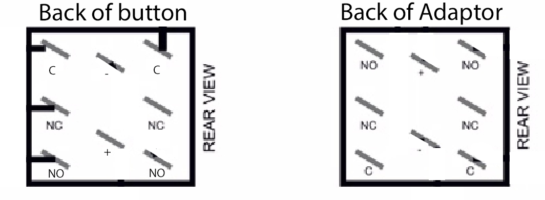
Here's the wiring diagram
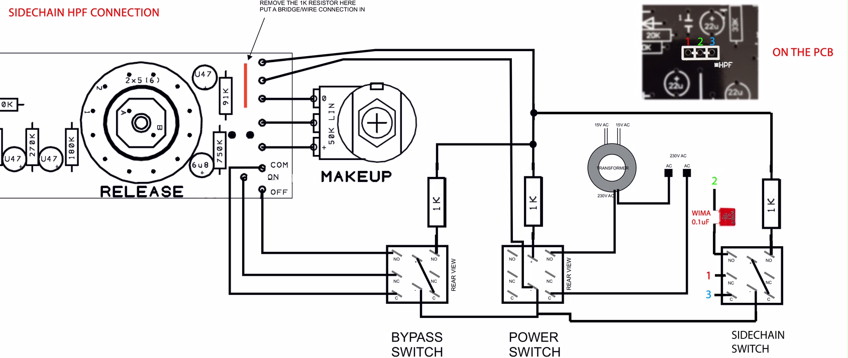
Looking at the wiring diagram below, I soldered it inversely to match the button markings... but... I don't know. Any help?
Here's what it looks like
Here's the wiring diagram
Alright, I had time to flip the wiring and it has the same behavior.
LEDs turn on in the push buttons when switched
Audio gets passed through, both channels work great and have ZERO noise
Turning on the compression (deactivating the bypass) still does nothing, also it might be good to mention the makeup gain does nothing. Probing the voltage of the makeup pot, it goes from 0V-12V just fine, so I'm not sure what's going on. Anyways, something that might be going on, I'm assuming there should be a voltage coming to "ON" and "OFF" and coming from "COM" so it can be managed by the switch. Well, there isn't a voltage coming from "COM" or going to "ON" or "OFF" . Looking at the schematic, COM goes to the ATTACK rotary, for some reason. Does this mean the switch isn't working?
aaruel said:Alright, I had time to flip the wiring and it has the same behavior.
LEDs turn on in the push buttons when switched
Audio gets passed through, both channels work great and have ZERO noise
Turning on the compression (deactivating the bypass) still does nothing, also it might be good to mention the makeup gain does nothing. Probing the voltage of the makeup pot, it goes from 0V-12V just fine, so I'm not sure what's going on. Anyways, something that might be going on, I'm assuming there should be a voltage coming to "ON" and "OFF" and coming from "COM" so it can be managed by the switch. Well, there isn't a voltage coming from "COM" or going to "ON" or "OFF" . Looking at the schematic, COM goes to the ATTACK rotary, for some reason. Does this mean the switch isn't working?
Return the unit to stock configuration, and see if it works. Its really hard to trouble shoot with mods added like this, since we can't be sure if its "just" the set-up of the switching.
Gustav
hello again people,
i thought the thread was dead but fortunately, i can see some people are still updating
i posted a situation in post Reply #7451 [ http://groupdiy.com/index.php?topic=47.msg794998#msg794998 ]. i believe i kind of solved it, but i am not sure if its plain luck. could anyone please kindly provide some feedback?
thank you!
regards.
Gustav said:aaruel said:Alright, I had time to flip the wiring and it has the same behavior.
LEDs turn on in the push buttons when switched
Audio gets passed through, both channels work great and have ZERO noise
Turning on the compression (deactivating the bypass) still does nothing, also it might be good to mention the makeup gain does nothing. Probing the voltage of the makeup pot, it goes from 0V-12V just fine, so I'm not sure what's going on. Anyways, something that might be going on, I'm assuming there should be a voltage coming to "ON" and "OFF" and coming from "COM" so it can be managed by the switch. Well, there isn't a voltage coming from "COM" or going to "ON" or "OFF" . Looking at the schematic, COM goes to the ATTACK rotary, for some reason. Does this mean the switch isn't working?
Return the unit to stock configuration, and see if it works. Its really hard to trouble shoot with mods added like this, since we can't be sure if its "just" the set-up of the switching.
Gustav
Just did, everything on it is working now!
Now I guess I should find out how this bypass switch should be wired. Something tells me it has to do with the two unmarked pins on the diagram circled below. It seems to be controlling the makeup gain (which would make sense). Any idea where I should wire those up to?
http://imgur.com/KK8iui3.jpg
Hi guys,
Just wanted to share a footage of my finished units, it's been a long way to get there but I finally did it.
One Gssl is with THAT2180B and a super sidechain, both pcbs from Gustav.
The other is with THAT2181C, with crush'n'blend rev6 from Lukas, Turbo from Expataudio and a lot of trimmers. I'm amazed with the sound and they are so helpful for my work as producer. Pretty happy with the switch I've added on the 47k from the threshold to bypass the resistor, so 2 different settings.. flexibility is everything these days Front panels and cases from Don Audio and Schaeffer.
Thanks to this forum, i've learned a lot about electronics in a short time. I screwed up many times.. but finally it gives adrenaline when it works and especially when you've made it with your two hands. Next step is the W492, PQD2, MS76, NetEQ...... ;D
Just wanted to share a footage of my finished units, it's been a long way to get there but I finally did it.
One Gssl is with THAT2180B and a super sidechain, both pcbs from Gustav.
The other is with THAT2181C, with crush'n'blend rev6 from Lukas, Turbo from Expataudio and a lot of trimmers. I'm amazed with the sound and they are so helpful for my work as producer. Pretty happy with the switch I've added on the 47k from the threshold to bypass the resistor, so 2 different settings.. flexibility is everything these days
Front panels and cases from Don Audio and Schaeffer. Thanks to this forum, i've learned a lot about electronics in a short time. I screwed up many times.. but finally it gives adrenaline when it works and especially when you've made it with your two hands. Next step is the W492, PQD2, MS76, NetEQ...... ;D
Attachments

aaruel said:Gustav said:aaruel said:Alright, I had time to flip the wiring and it has the same behavior.
LEDs turn on in the push buttons when switched
Audio gets passed through, both channels work great and have ZERO noise
Turning on the compression (deactivating the bypass) still does nothing, also it might be good to mention the makeup gain does nothing. Probing the voltage of the makeup pot, it goes from 0V-12V just fine, so I'm not sure what's going on. Anyways, something that might be going on, I'm assuming there should be a voltage coming to "ON" and "OFF" and coming from "COM" so it can be managed by the switch. Well, there isn't a voltage coming from "COM" or going to "ON" or "OFF" . Looking at the schematic, COM goes to the ATTACK rotary, for some reason. Does this mean the switch isn't working?
Return the unit to stock configuration, and see if it works. Its really hard to trouble shoot with mods added like this, since we can't be sure if its "just" the set-up of the switching.
Gustav
Just did, everything on it is working now!
Now I guess I should find out how this bypass switch should be wired. Something tells me it has to do with the two unmarked pins on the diagram circled below. It seems to be controlling the makeup gain (which would make sense). Any idea where I should wire those up to?
http://imgur.com/KK8iui3.jpg
Great news - problem isolated to the alternative switching.
The switching has been covered numerous times in this thread - sorry, I dont have direct experience setting it up.
Gustav
Similar threads
- Replies
- 11
- Views
- 7K
- Replies
- 12
- Views
- 1K