GSSL HELP THREAD!!!

GroupDIY Audio Forum

Help Support GroupDIY Audio Forum:

This site may earn a commission from merchant affiliate links, including eBay, Amazon, and others.
aaruel said:
Return the unit to stock configuration, and see if it works. Its really hard to trouble shoot with mods added like this, since we can't be sure if its "just" the set-up of the switching.

Gustav


Just did, everything on it is working now! :D

Now I guess I should find out how this bypass switch should be wired. Something tells me it has to do with the two unmarked pins on the diagram circled below. It seems to be controlling the makeup gain (which would make sense). Any idea where I should wire those up to?

http://imgur.com/KK8iui3.jpg


Great news - problem isolated to the alternative switching.

The switching has been covered numerous times in this thread - sorry, I dont have direct experience setting it up.

Gustav


Alright I figured out a solution, with a compromise however. The desired operation of the switch is the light, compression, and makeup gain off when normal, and on when switched, however it's a DPDT switch so only two of those things can happen. Since I would rather vie for correct non-aestetic operation, I opted for the makeup gain and compression to be controlled with the switch, resulting in a diagram like this

--> http://imgur.com/scjMxAP.jpg <--

Note the NC and NO are flipped because I want the compression enabled when switched. The compromise being the light will stay on all the time, but I'd take that for a properly working unit. If you want the light to switch on and off, just wire it normally and bridge two wires (if you look on the schematic you'll see they are the two pads connected to the makeup gain pot output). Another problem I had when wiring up was the compression didn't work at first, which confused me. I then tried to do a continuity test on the switch and found out NO wasn't working on one of the poles. Since the makeup gain didn't need a NO state, I just flipped the wiring and everything worked fine. Hope this helped some people looking for answers.

hello great diagram! I am having problems with my 2 square push buttons as well. I have the super side chain  and I believe the "com, on, off" from the control panel routes to the super side chain. I am some what new at DIY but am smart I think lol. any who would you know how to hook up from or with the SSC included?!?! thank you in advance!!!
Jim
 
This will be a dumb question but for the rotary switch on the Side chain what exact is "TL, TM"? I am assuming the EXT is for the back xlr side chain portion? Thank you in advance

Jim
 
offthewallstudio said:
This will be a dumb question but for the rotary switch on the Side chain what exact is "TL, TM"? I am assuming the EXT is for the back xlr side chain portion? Thank you in advance

Jim


You can ask google for this :)
 
they are mod for the sidechain, to compress regarding a curve based on the loud freq or the mid freq...just try and you will hear.
 
offthewallstudio said:
I did and found nothing :( I found out how to but what exactly do these functions do? thanks
Search for thrust filters (API).


One link here:


http://www.soundonsound.com/sound-advice/q-what-does-api-2500-compressors-thrust-control-do


Best regards,


Udo.
 
kante1603 said:
Search for thrust filters (API).


One link here:


http://www.soundonsound.com/sound-advice/q-what-does-api-2500-compressors-thrust-control-do


Best regards,


Udo.

Awesome!! Thank you!!!

I am going to wire up my 2 square push buttons for compressor and for power. I have a diagram I found in this thread but then I heard others having issues. Any one with experience on this doc?
 
hugo said:
On the back of the push button, the 2 pins at the center are marked + and - for the internal led. on the sides you have two classic switchs (Common marked as C, NC you will not use, and ON when the button is pushed.

first goal : you have to feed the 2 leds with the same power source..you will find it marked as "led" on your sc board..it is time to use it.

- There is a pin marked + on your push buttons.. Connect a 1.5k here for both.
- connect the "-" together (pin - of the power button, pin - of the comp button, and the - of the sc led.
- connect the top left pin to the
Power button : connect  the top left pin with the + of the led.
- connect the + of the "led" from your sc board to the pin bottom left.
The goal here is to have the led illuminated only when the button is pushed.

- Connect the top right pin to the Neutral of IEC inlet
- Connect  the bottom right pin to the primary of your toroidal
- Your other primary  wires should be connected to the IEC inlet already

TAKE THE BYPASS SWITCH :

- Wire the same for the led ( you will need to cut the wire between the "+"  you already soldered, to split it and feed the two buttons).
On your sc board, there is a bypass marked. Connect one hole to the top right, and the other hole to the bottom right pin.

Hi Hugo,
i got about half way but now have some questions:

i see others connecting the buttons to the main control panel

- There is a pin marked + on your push buttons.. Connect a 1.5k here for both. i did this but dont know what to connect to these 2 ends
- connect the "-" together (pin - of the power button, pin - of the comp button, and the - of the sc led.
- connect the top left pin to the  ----where you going to type something here of is that a typo?
Power button : connect  the top left pin with the + of the led.
- connect the + of the "led" from your sc board to the pin bottom left.  the +led from the super side chain  needs to connect to both top left and bottom left to the power button?
The goal here is to have the led illuminated only when the button is pushed.

- Connect the top right pin to the Neutral of IEC inlet  is this ground of the power supply?
- Connect  the bottom right pin to the primary of your toroidal
- Your other primary  wires should be connected to the IEC inlet already

TAKE THE BYPASS SWITCH :  i take it this is the "compressor" button?

- Wire the same for the led ( you will need to cut the wire between the "+"  you already soldered, to split it and feed the two buttons).
On your sc board, there is a bypass marked. Connect one hole to the top right, and the other hole to the bottom right pin. i am sorry but i do not follow these 2 steps


thank you Hugo, this info is much much appreciated. please forgive me as i am not a professional but semi lol
 
Im so close to done. I need help with the 2 push buttons in the front to correspond with the super side chain psb. I drew a diagram of what i currently have. If someone could please help think i might be able to use it today!  Please see photo. Thank you!!!
 
Hi There,

i have started my first high end studio gear diy-project.
Target: Build my own GSSL with SC.  ;D

So... to be prepared for some future mods:

Expataudio´s Turbo Mod requires a second SC board.
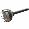
The side chain switch (8 steps) is a single switch. 
t_20624-05-01-01.gif

I need to replace this one with a dual switch (8 steps) for each sc channel, right?

Some hints to find the right one?


Thanks a lot,
ToBSn
 
Hey all! I am done with the project however i need to connect the power push button and i am stumped.  The compressor button works and lights up
The photo should be my.last step but cant figure out what wires to use from the power supply
 
offthewallstudio said:
Hey all! I am done with the project however i need to connect the power push button and i am stumped.  The compressor button works and lights up
The photo should be my.last step but cant figure out what wires to use from the power supply

Hi,

it´s perfect documented in the "Universal Wire Guide".

https://pcbgrinder.com/download/PDF/WIRE_GUIDE_DONE.pdf

Good luck.  :)
 
Searched thru and found one hit from 11 years ago that was somewhat similar but thought I'd ask-

if you want the short version of my question, skip to the bottom :)

I'm modding an existing GSSL with it's own PCB design that includes the turbo mod on it's main board. The person I'm modding it for wanted sidechain filtering  ability added on. I used more or less the same schematic as this one- http://sounddiy.free.fr/images/SSL/Doc/Sidechain/Sidechain_Sch.pdf

with the exception of leaving out a few of the filters. and I duplicated the circuit since this is a turbo GSSL. The compressor also already has external sidechain ability, so I wired it so that when you engage the external, the existing DPDT relay switches over to the new sidechain filter board.

when I connect the output of the filter board to the main board (at the 47k resistors prior to the VCAs), the unit goes into a strange behavior where the GR shown on the meter reads inversely proportional to the threshold pot setting.

TLDR since this is kind of an oddball in that I didn't build the compressor that I'm troubleshooting, I'd like to know if anyone can shed light on what conditions would have to be in order to make the GR inversely proportional to the threshold setting? Just looking for where to start looking, and I've never built a GSSL before. Sorry if this is a dumb question.

Thanks!
 
i have big problems, just hooked it up. only 1 side seems to be receive and exporting out a signal. also the vu meter does not move and also i dont hear any compression. 😞 ... not having a LED light working would not cause this issue right?
the LED Meter on the ssc board was never hooked up. as it is hooked up from the control pcb, could this be the issue? 😞
thanks,
Jim
 
Hello all!!! I have the4 GSSL with the SSC MOD. I am done with it! I have 2 major problems i really need help with! The left side channel is not receive any audio but the right channel is! Also i am not seeing any compression nor do i hear any :( .... the meter is set up from the main pcb control panel not from the ssc pcb. PLEASE HELP ME!!!!! I WILL BE POSTING PICS BELOW
 
Back
Top