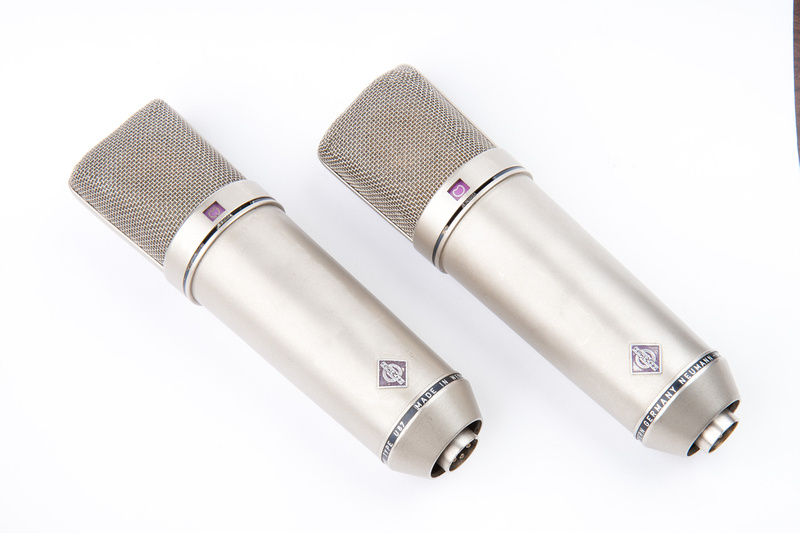
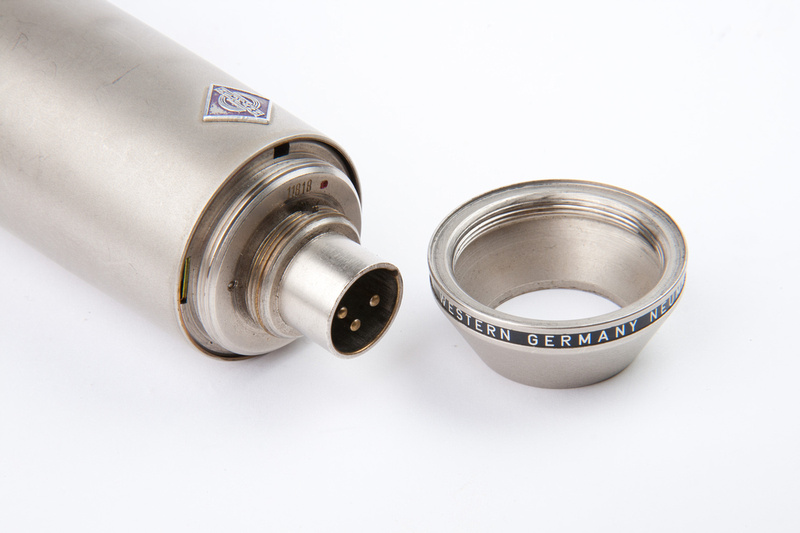
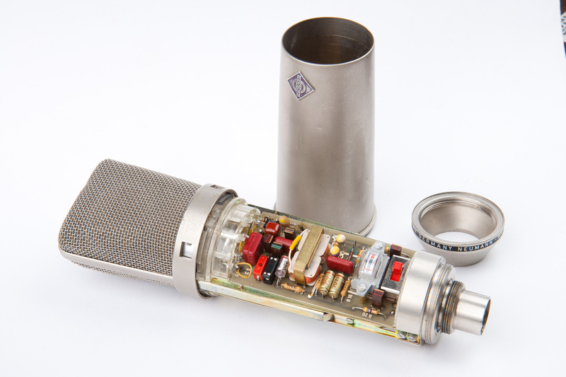
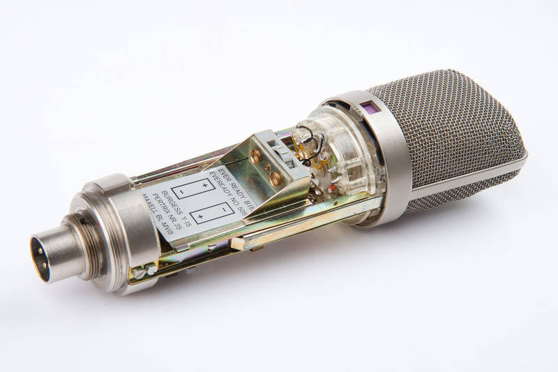
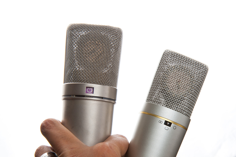
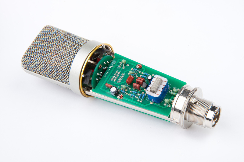
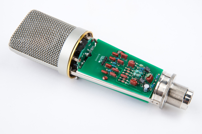
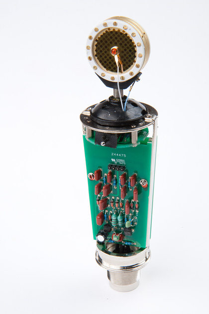
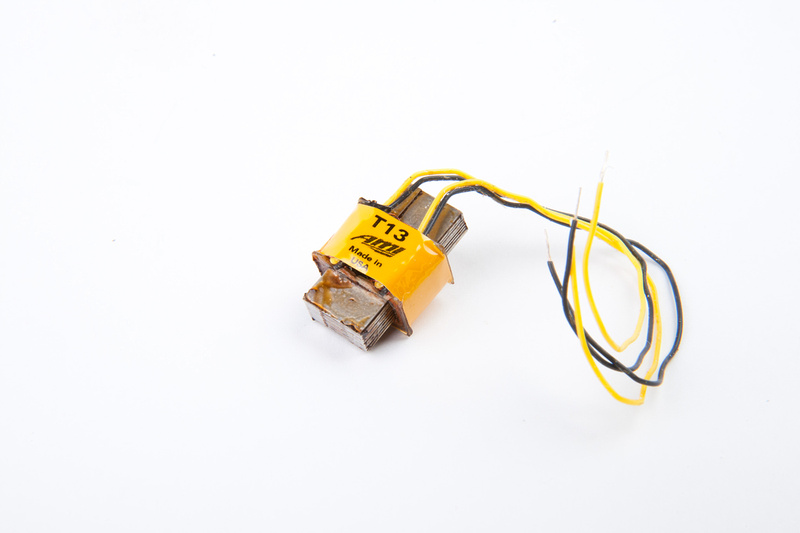
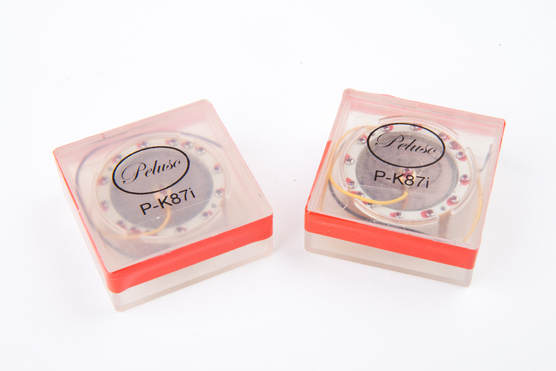
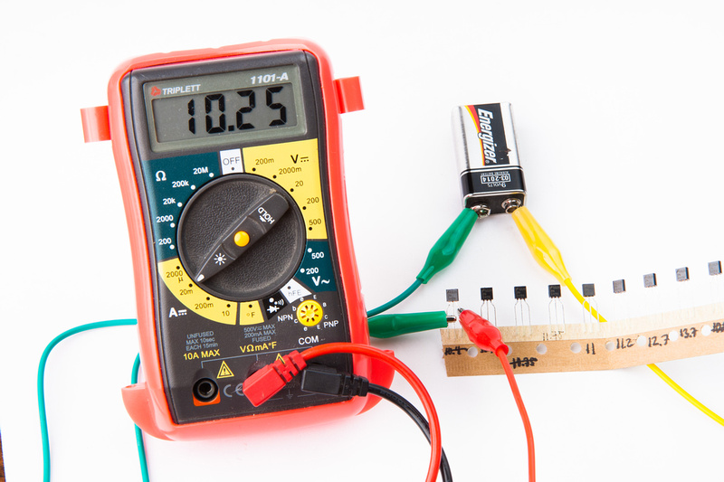
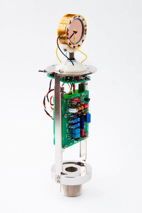
on with the build. . . it was really nice that folks were able to find a documentation error in the ami t13 transformer lead colors recently and resolve the low output problem a lot of folks were experiencing. Of the 10 fairchild 2n3819 jfets I purchased from the BOM, the lowest IDSS was about 10.2ma . I did order a pile more of these on Ebay to try and find a lower IDSS copy, but I think the build should be fine with this one. I track drums a lot and have good preamps with plenty of gain. . . actually, a few of my preamps sound better at higher gain, so if the trade is higher dynamic range for overal gain, I'll take dynamic range.
I used the method described by Matador in the build thread:
Short gate and source together (pin 1 and pin 2) and connect to the negative side of a 9V battery. My multimeter in current sensing mode is hooked up between the drain (pin 3) and the positive side of the 9V battery and I measure the mA and make note. I found it easy to leave the jfets in their bulk packaging and just write values on the cardboard.
As noted, all of my current 10 jfets were between 10 and 13 mA IDSS.
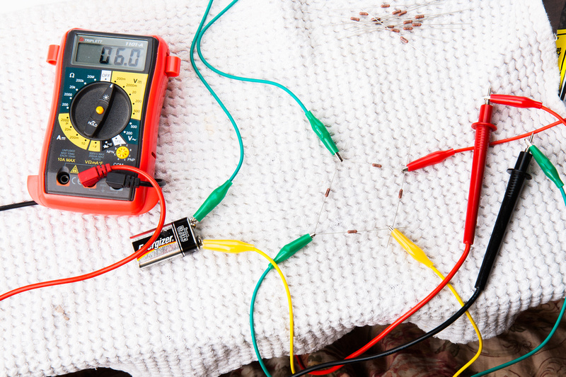
Next, reading the build tips, I realized that R18 and R19 need to be matched to .4% and my cheap multimeter is not up to that task. So, I went on google and found this method that uses a wheatstone bridge.
http://www.head-fi.org/t/295983/tutorial-how-to-match-resistors-up-to-0-01-using-a-cheap-dvm
I'm not sure how good it is, but I was certainly able to make differentiations between my 40 1% resistors.
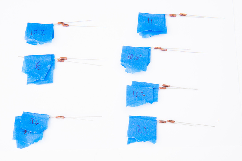
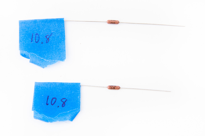
Utilizing the 1st half of the methodology, I was able to find 7 pairs to the limits of my meter's sensitivity. Hopefully these are within .4%
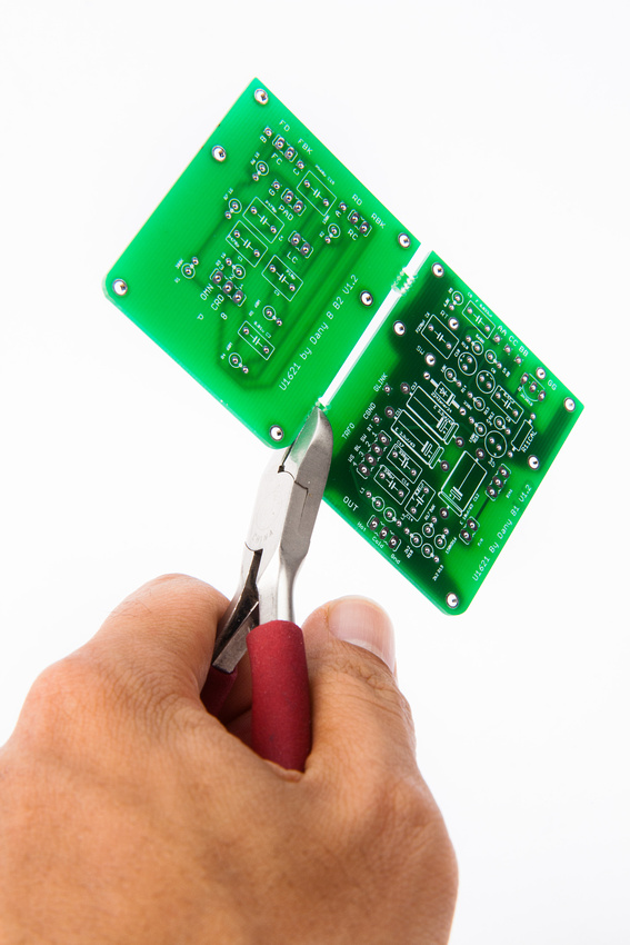
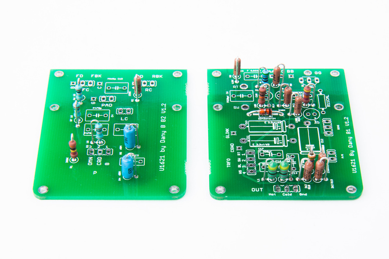
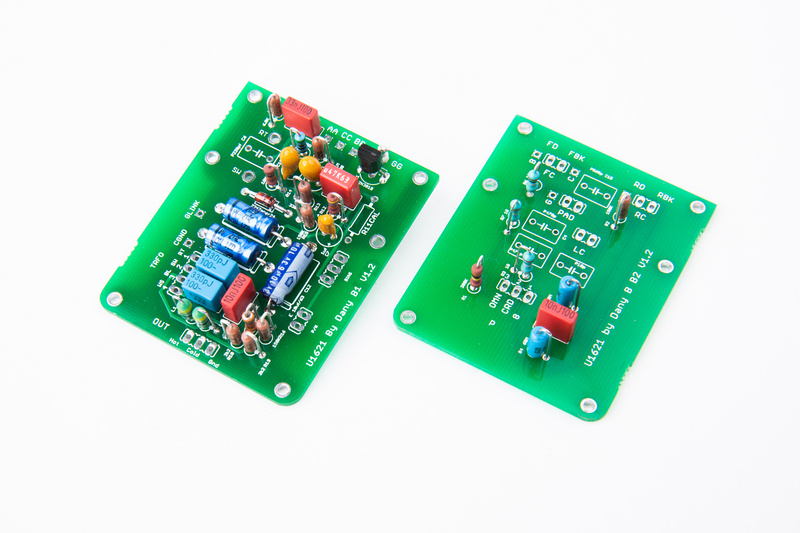
So, after all that, I finally get to the pcb's. Note, I changed bodies mid-stream on this project so we are now utilizing poctop's large version of the boards designed to fit ShuaiYin SYT-5 bodies.
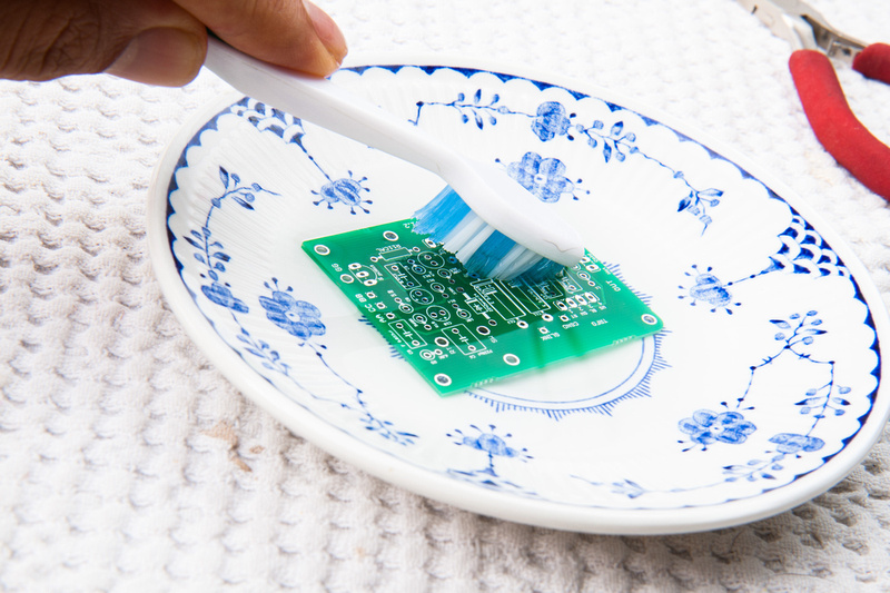
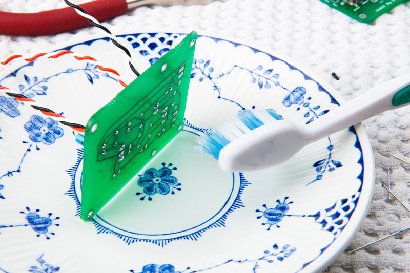
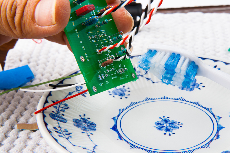
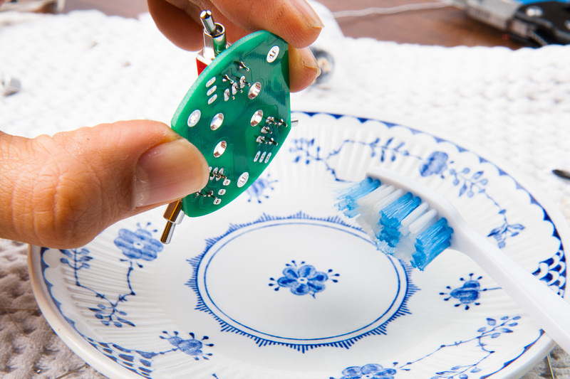
Since I started building mics, and read about high impedance sections of the circuit needing to be clean of solder flux, I've been super-obsessive about cleaning everything. I found some 91% isopropyl alcohol at the convenience store and it's been working well for me in conjuction with a toothbrush.
The first of many dips into the cleaning solution.
I select one of my newly matched pairs of resistors and begin populating.
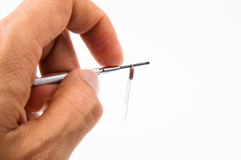
I use the smallest screwdriver shaft that I have to help bend the resistor leads nicely.
And, I start to populate referring to the BOM. I did not sort all of my components onto a piece of paper like I usually do because all of my parts were still in their Mouser Electronic baggies and clearly labelled.
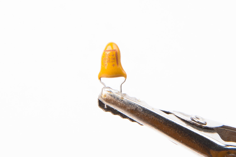
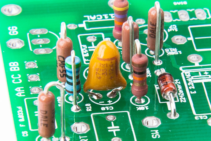
Next, I move to the capacitors. The tantalum caps have polarity, so heed the markings even though they are small. I am building per the "original" options on the BOM, so I will be using tantalum and polystyrene capacitors.
The electrolytics also have polarity, so make sure you get the "+" and "-" sides correct.
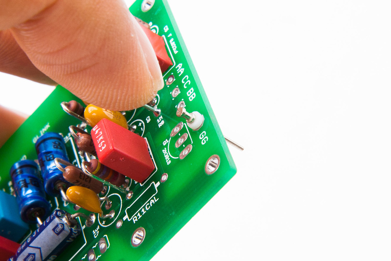
The teflon isolation pin is press-fit into the provided hole.
and, most items are populated with the exception of the polystyrene capacitors. I read that those are sensitive to alcohol, so I wanted to clean the boards thoroughly before I install those.
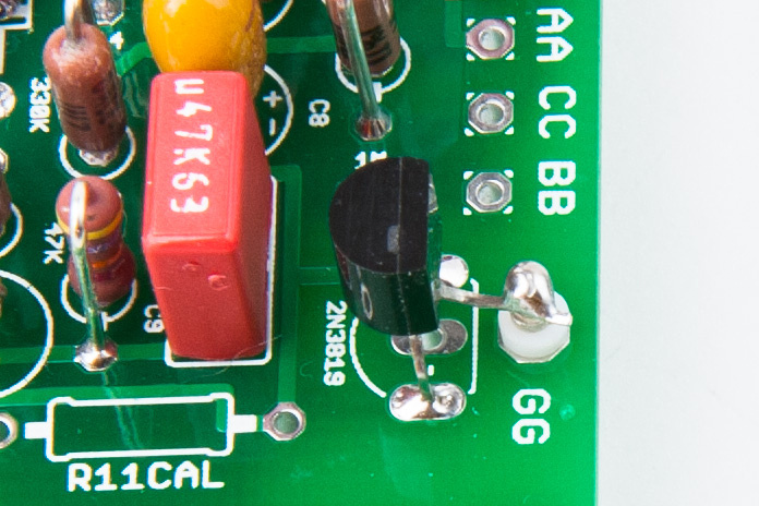
Note, the drain leg of the jfet is soldered to the teflon isloating pin and not to the through hole on the PCB.
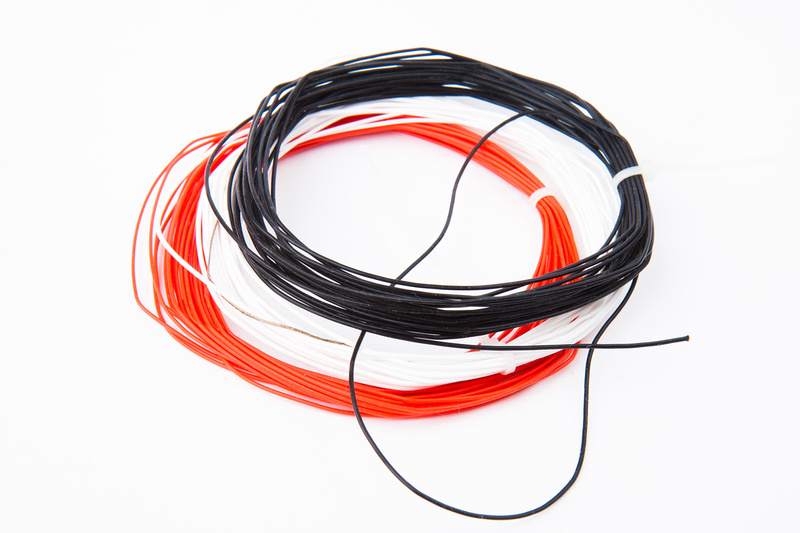
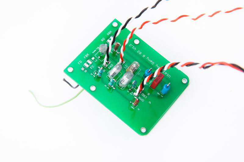
Next, I pull some 24 AWG silver teflon wire.
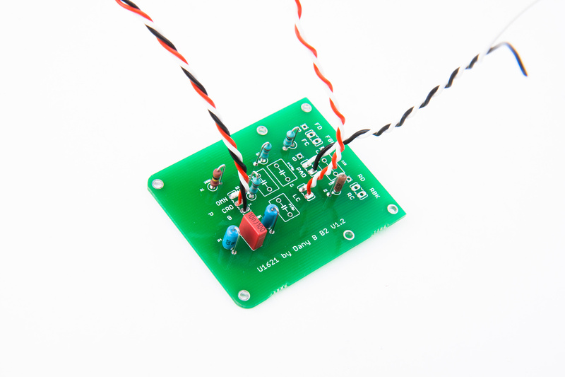
and connect my wires for switches (Low Cut, Pad, and Pattern).
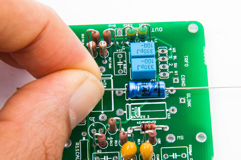
Before the Styrenes go in, I clean my PCB with alcohol and a toothbrush.
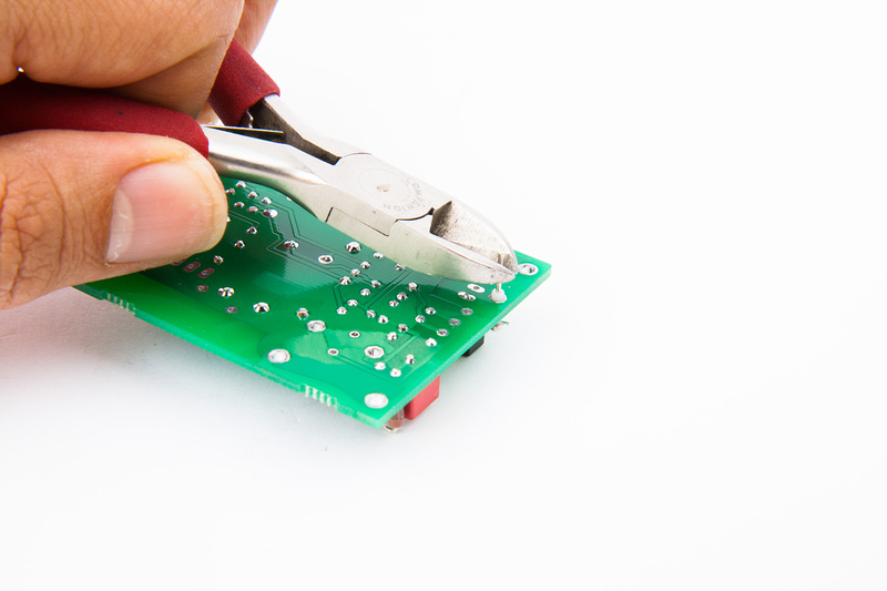
Next, I trim the pin of the teflon isolator so the PCB's will clear each other when mounted.
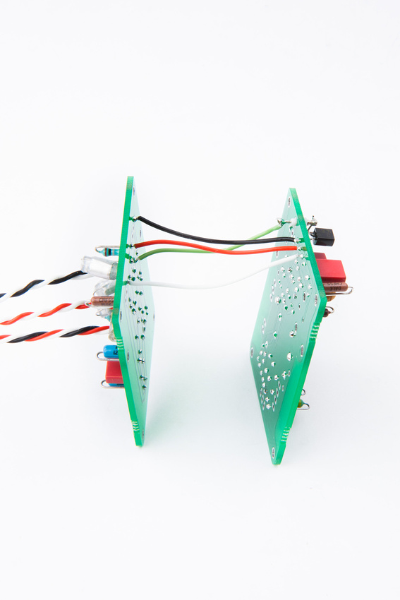
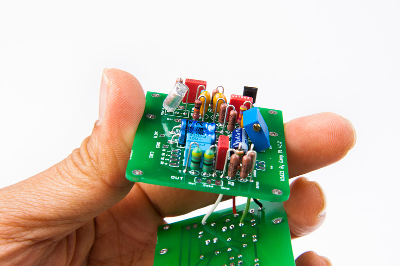
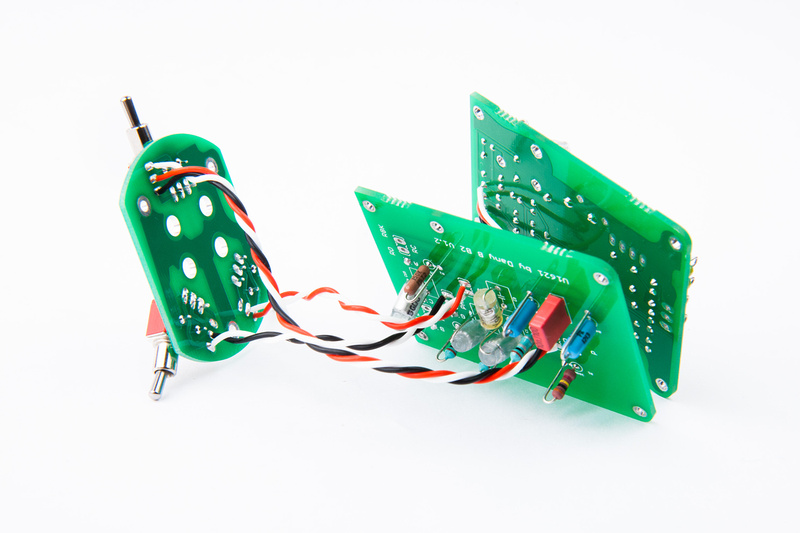
. . . and install jumper wires to connect the 2 pcb's together.
Every time I solder, I leave flux on the PCB, so I clean whenever possible.
And styrene capacitors are populated.
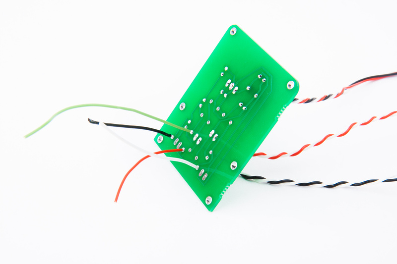
And, at this point, I complete the connections between the 2 pcb's. A to AA, B to BB, C to CC, and G to GG. Note, G attaches to the teflon isolated pin.
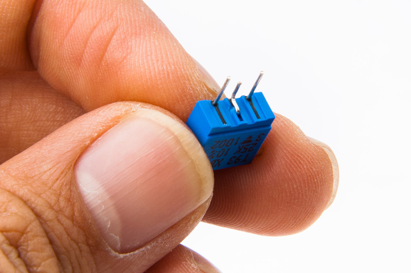
The large PCB leaves provision for separate installation of the bias potentiometer. Unfortunately, the original BOM had a trim pot spec'd that had staggered leg configuration instead of straight like on the PCB. I simply bend the center pin a little bit to fit the straight hole pattern.
with such a large diamter microphone body, I doubt it will be a problem, but I install the trim pot at an angle to help with component clearance near the edge of the PCB.
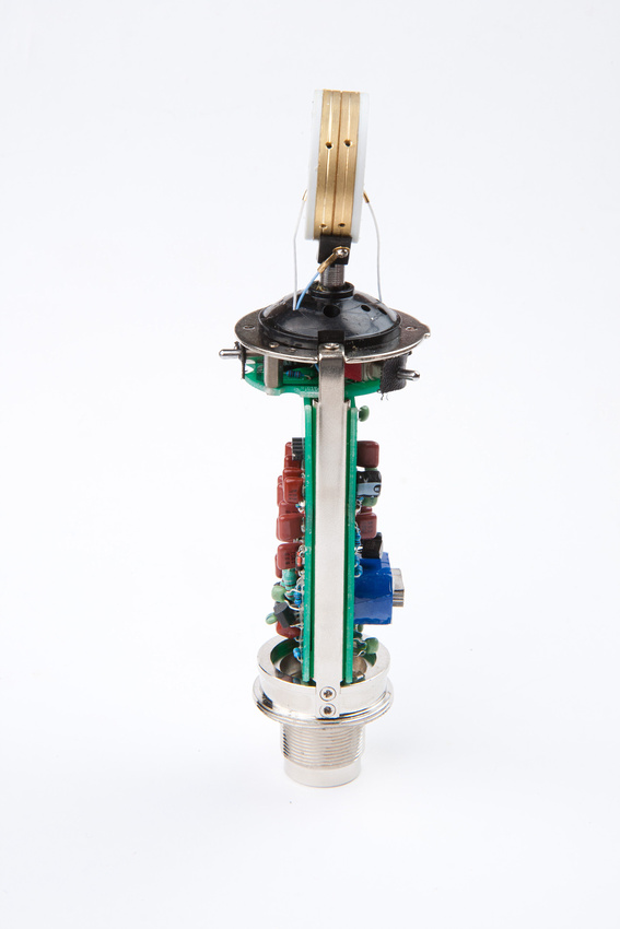
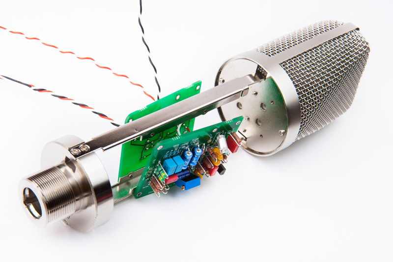
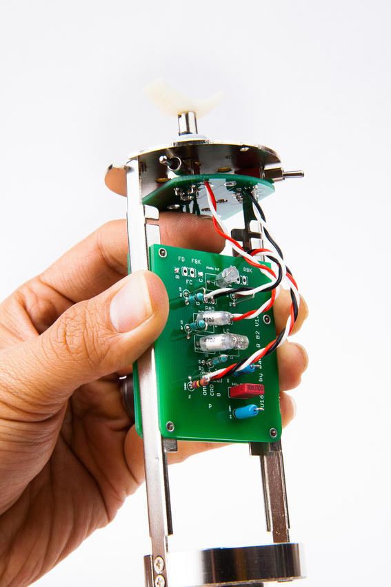
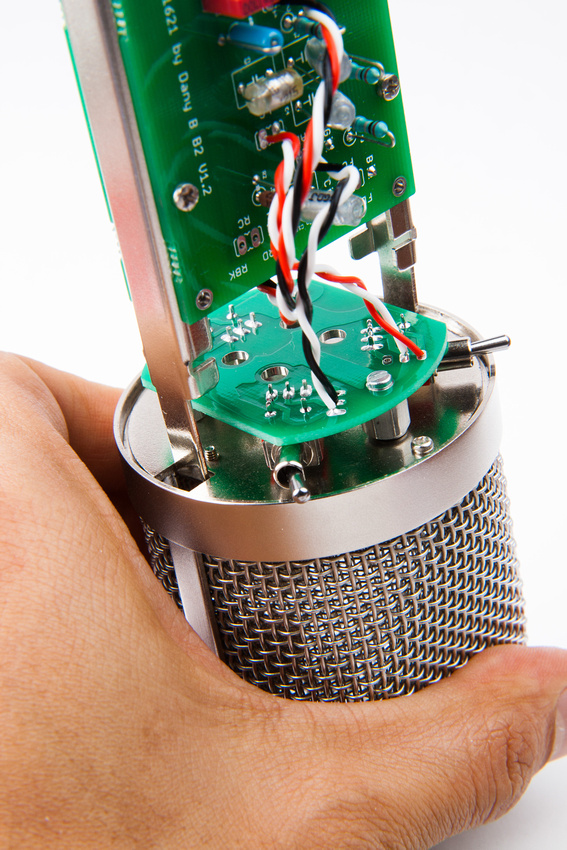
And, at this point, I make a quick check just to see where everything will sit inside the microphone's frame rails.
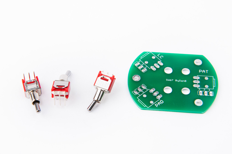
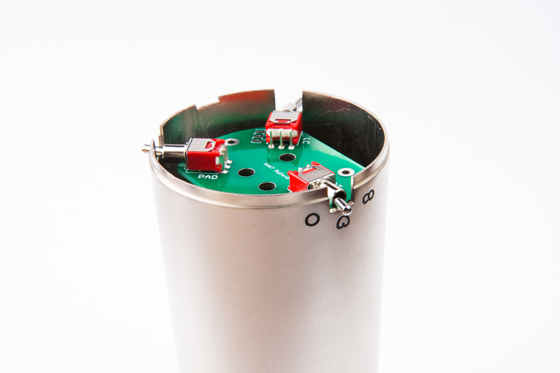
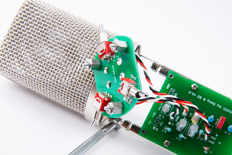
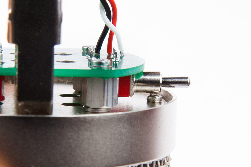
Next, I pull a switch mounting pcb which I have a supply of in stock from poctop as well as the 3 switches provided by the factory. 2 of the switchs are on-on type and one of them is on-off-on for the pattern adjustment.
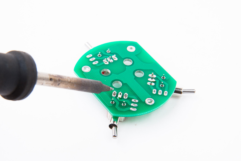
I solder a single pin on each of the switches to begin so I can make small adjustments and line them up perfectly with the screen printing on the front side.
After confirming alignment, I solder the remaining legs and keep my microphone outer tube handy because I will refer to the screen print markings on the body to make sure I wire up the switches properly.
And, I take the opportunity to thoroughly scrub my switch PCB with alcohol.
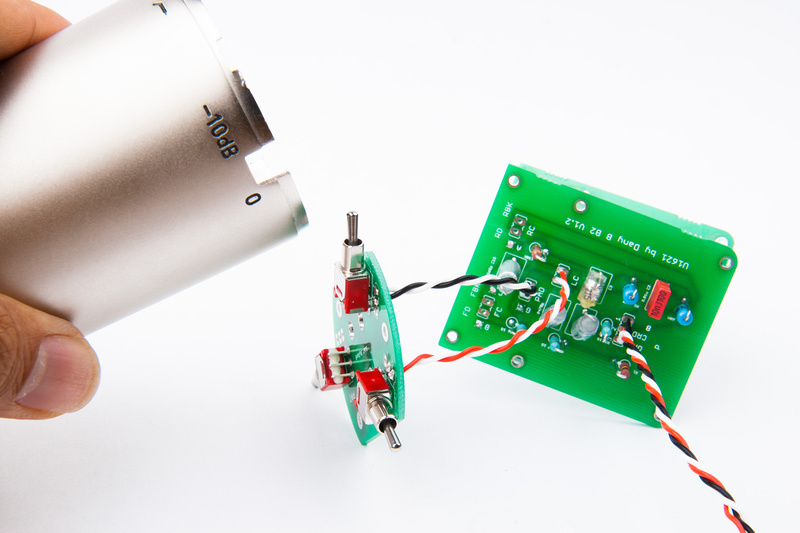
And, I begin wiring the switches checking carefully to make sure my switching corresponds to the markings on my particular microphone body.
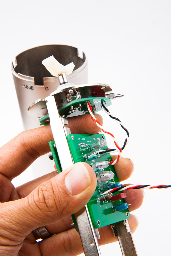
A quick test fit confirms my wire lengths are reasonable. I want the runs to be relatively short, but also want to be able to move the boards a bit for diagnostics and repair in the future.
All 3 switches are now wired up.


