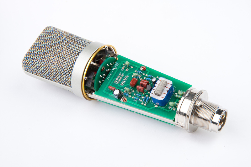
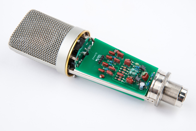
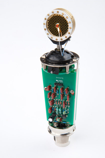
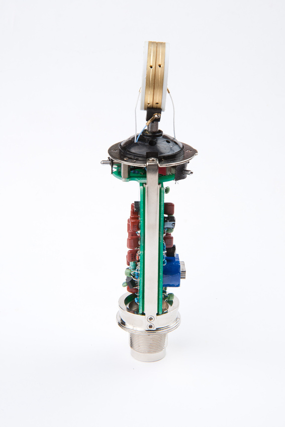
Newbie builds U87 clone

GroupDIY Audio Forum

Help Support GroupDIY Audio Forum:

This site may earn a commission from merchant affiliate links, including eBay, Amazon, and others.

chunger

Well-known member
Joined
Apr 21, 2008
Messages
1,036
Location
Northern California
I've been trying to find a few projects to improve the microphone options in studio without breaking the bank and after reading through a lot this thread:

http://www.groupdiy.com/index.php?topic=48030.0

. . . decided to go ahead and build poctop's U87 vintage circuit microphone.  The documentation, BOM, and various options for capsule, transformer, and internal components were well laid out and ordering parts was actually as easy as clicking on a Mouser BOM and ordering 1 polystyrene capacitor from another source linked to in the BOM exel file.  There will be a few tricky parts for largely electronically non-literate folks like myself to do like selecting FETs and calibrating some internal components, but I figure I would give it a go and learn something along the way.

 
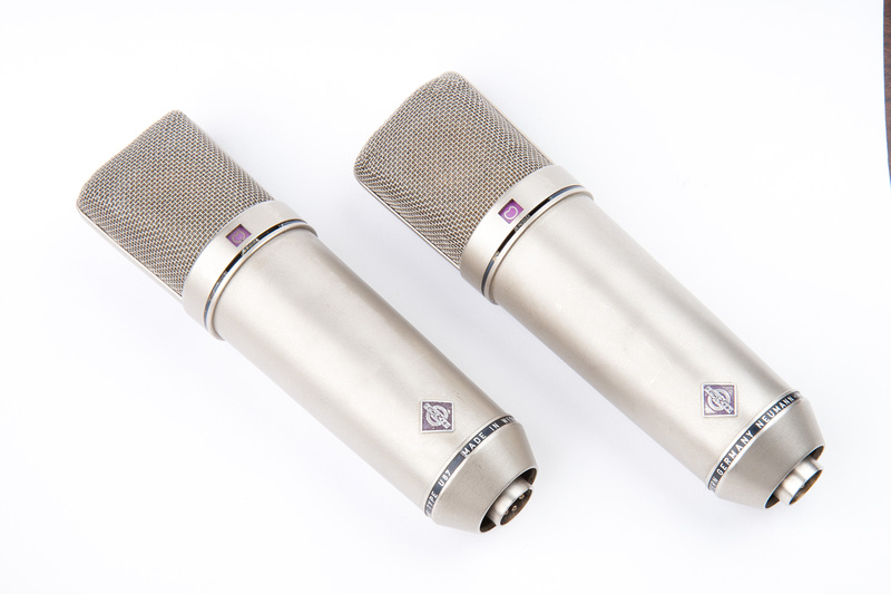
Since this is a vintage circuit reproduction, I asked around and a friend had a pair of vintage U87 mics that are largely unused so I asked if I could borrow them to use as a baseline to evaluate how successful these clones are.

p638741574-4.jpg


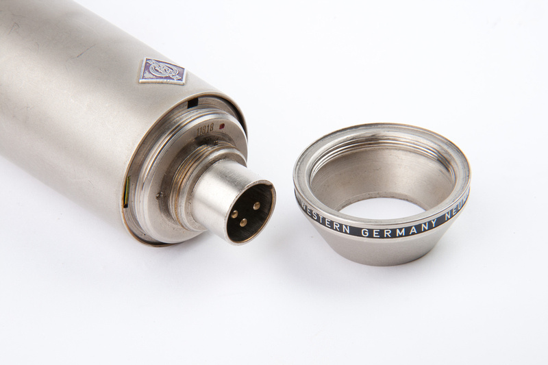
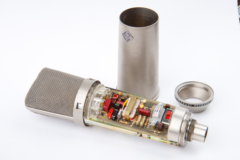
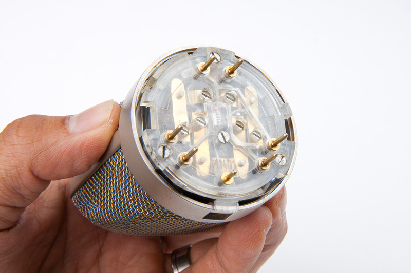
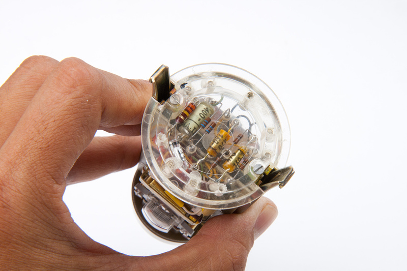
I do not get hands-on very many vintage microphones, but the build quality on these old mics seems absolutely fantastic from design to machining.  Certainly these mics have seen their share of use, but it's fun to poke around and see how things were done "back in the old country"  ::)

p805793345-4.jpg


p823460023-4.jpg


p1048292102-4.jpg


p792652262-4.jpg


It looks like some of the high impedance portions of the circuit were built point to point "floating in the air"

p988700756-4.jpg


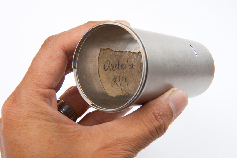
Looks like this mic was overhauled before I was born.

p1009482962-4.jpg


Fun stuff!
 
The donor body I'm using for this build was sourced in the white market from cmuller0420

http://www.groupdiy.com/index.php?topic=48552.0

and is an ISK BM600 i believe that is unmarked.  Alternately, I'm importing a few Alctron MC-330 that look to be cut from the same tooling if not the same mic.  Hard to tell if there are differences until I get them in hand.

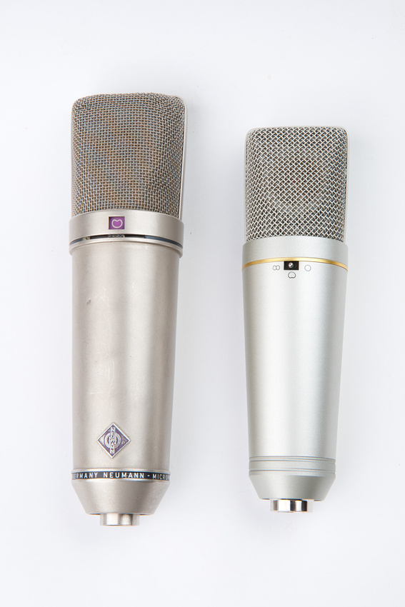
At any rate, here is the donor body next to the real thing.  You can see as typical with many of the common U87-ish clones, it is quite a bit smaller in every dimension.

p1052925085-5.jpg


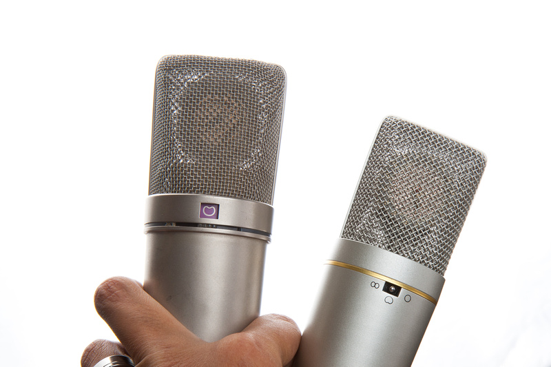
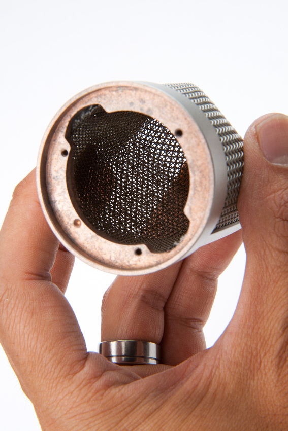
And the headbasket mesh sizing is different.  Thicker, more widely spaced mesh seems to be used on both the inner and outer layers.

p997849620-4.jpg


Internal construction. . . well, just doesn't feel as cool since I was just poking around the vintage mic.  But, all seems strong and functional which is the point.  It just needs to hold stuff together, and in the end, the only thing that matters to me is long-term durability and sonics.

p990530097-4.jpg


p945644497-4.jpg


p824515534-4.jpg


But, the capsule seems to have been installed very crooked, and it may not be a simple matter to adjust the mount to fix it.  This may cost me a little extra from the get-go to buy another mount.  It appears the post was glued into the rubberized suspension portion of the mount crooked.  Certainly no signs of care during assembly  :eek:

p562058765-5.jpg


The headbasket is brass and has been painted. . . if it had been plated, the plating would cover the insides as well as the outside.

p901944967-5.jpg


The stock capsule.

p844565270-4.jpg


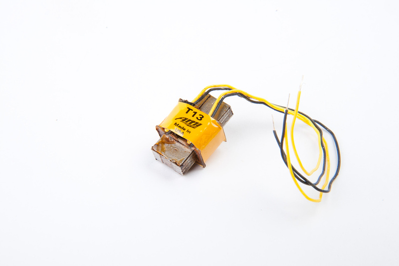
I will be using the AMI Tab-Funkenwerk T13 as this is reported to be the best vintage reproduction iron though the Cinemag is also a finely crafted and proven performer at half the cost.

p651365988-4.jpg


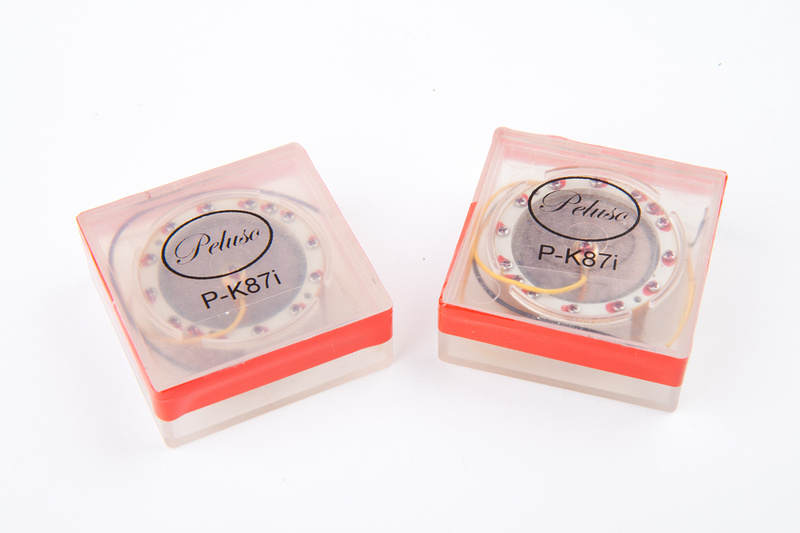
I will also be using Peluso's K87i capsules for this build.

p1047922415-4.jpg
 
Hey Chunger.
This build is fun and not super hard. The MK47 was definitely more of a challenge. The trickiest part is the biasing. Do you have a scope and function generator?
I too am about to do another U87 using the BM-600 from cmuller so I'm sure your thread will help as well as maybe I can contribute some tricks.
Can you do me a favor and post a nice closeup of one of your PK-87 capsules? I have yet to see a really good shot of one and since your newbie threads are great for these types of photos...
What made you decide to go with the Pelusos? Eric's (tskguy) capsules that are 100% USA made are pretty awesome.
Anyway, good luck and I will be checking back frequently.

Dave
 
well shoot. . . I didn't even know tskguy was making capsules.  Can you link?  I went with the Peluso because I thought it was a choice between that and the microphone-parts.com ones which I think are high-end Chinese.
 
Chunger,

I would love to sell you a capsule, I havent really done any real advertising, I havent really needed to yet. I have some sound samples and pictures in the u87 thread. Wave and I both posted some samples of some comparisons with his mic as well as my personal mic with one of my capsules in it.  Let me know!
Eric
 
wave said:
Hey Chunger.
This build is fun and not super hard. The MK47 was definitely more of a challenge. The trickiest part is the biasing. Do you have a scope and function generator?
I too am about to do another U87 using the BM-600 from cmuller so I'm sure your thread will help as well as maybe I can contribute some tricks.
Can you do me a favor and post a nice closeup of one of your PK-87 capsules? I have yet to see a really good shot of one and since your newbie threads are great for these types of photos...
What made you decide to go with the Pelusos? Eric's (tskguy) capsules that are 100% USA made are pretty awesome.
Anyway, good luck and I will be checking back frequently.

Dave

I do have a function generator and a scope that are borrowed from the same friend who is loaning me the 2 vintage U87's for testing :)  So perhaps with a little bit of Q & A or digging through the thread, I should be able to dial in this build.
 
David R. said:
Chunger - official photographer of the D.I.Y. build.

Indeed.  For those who haven't seen them, Chunger's "basses for newbies" threads over at Talkbass are downright legendary, spanning thousands of pages.
 
Hey Chunger,
How is your build going? Just wanted to comment and say I'm doing this same build and an MK47 simultaneously and your MK47 thread was incredibly helpful, thanks! Looking forward to seeing your progress on this.
 
I was just working on this build the last couple of days.  I did change gears a bit and am utilizing the larger ShuaiYin SYT-5 type microphone body.  I horse traded my BM600 bodies with tskguy for one of his nice U87 capsules to try, and I must say, the machining and craftsmanship on those are tremendous for the price.  Really top tier attention to detail.  No corners cut.

More to come soon.
 
Eric's capsules are totally top notch and sound AMAZING. I just put some new clips up in the DU67 build thread.

Dave
sorry I just had to interject this after reading your comment chunger!
 
on with the build. . . it was really nice that folks were able to find a documentation error in the ami t13 transformer lead colors recently and resolve the low output problem a lot of folks were experiencing.  Of the 10 fairchild 2n3819 jfets I purchased from the BOM, the lowest IDSS was about 10.2ma . I did order a pile more of these on Ebay to try and find a lower IDSS copy, but I think the build should be fine with this one.  I track drums a lot and have good preamps with plenty of gain. . . actually, a few of my preamps sound better at higher gain, so if the trade is higher dynamic range for overal gain, I'll take dynamic range.

I used the method described by Matador in the build thread:

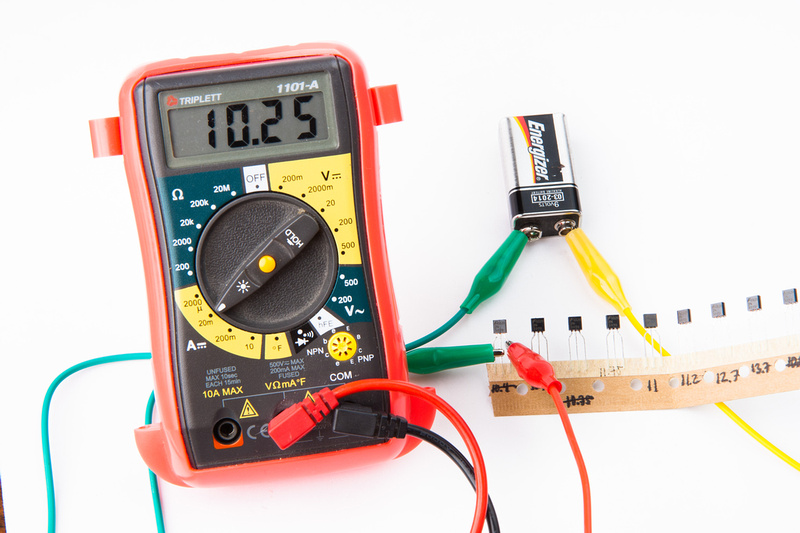
Short gate and source together (pin 1 and pin 2) and connect to the negative side of a 9V battery.  My multimeter in current sensing mode is hooked up between the drain (pin 3) and the positive side of the 9V battery and I measure the mA and make note.  I found it easy to leave the jfets in their bulk packaging and just write values on the cardboard.

p1289025382-4.jpg


As noted, all of my current 10 jfets were between 10 and 13 mA IDSS.

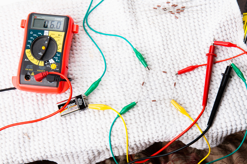
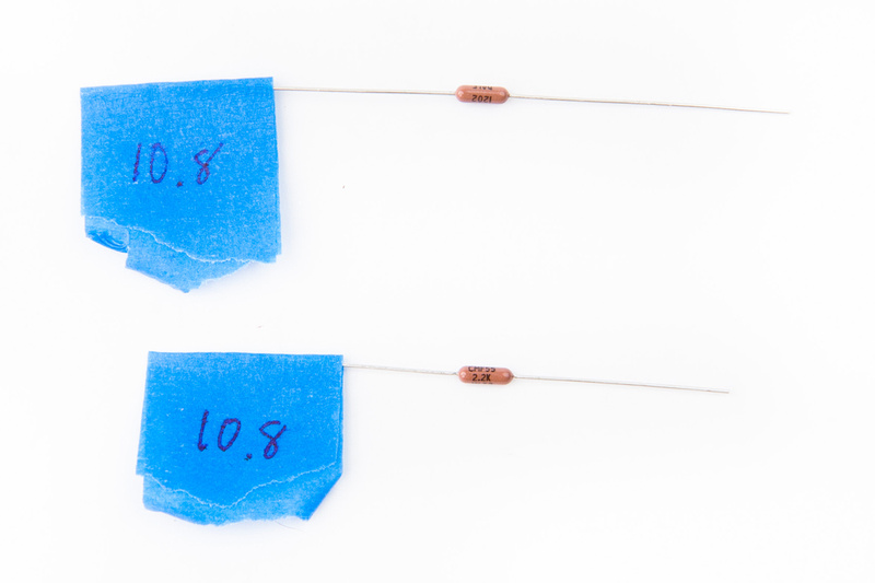
Next, reading the build tips, I realized that R18 and R19 need to be matched to .4% and my cheap multimeter is not up to that task.  So, I went on google and found this method that uses a wheatstone bridge.

http://www.head-fi.org/t/295983/tutorial-how-to-match-resistors-up-to-0-01-using-a-cheap-dvm

I'm not sure how good it is, but I was certainly able to make differentiations between my 40 1% resistors. 

p1289025728-4.jpg


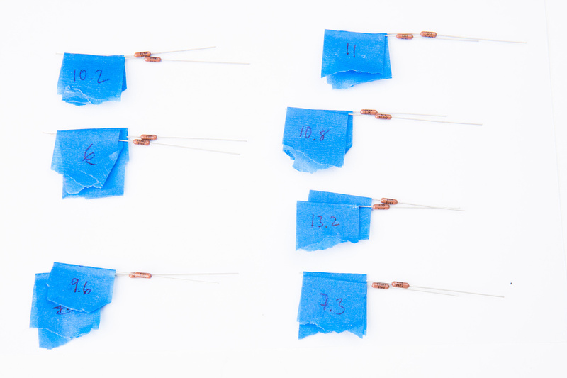
Utilizing the 1st half of the methodology, I was able to find 7 pairs to the limits of my meter's sensitivity.  Hopefully these are within .4%

p1289026620-4.jpg


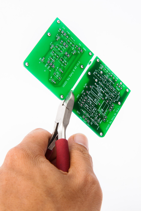
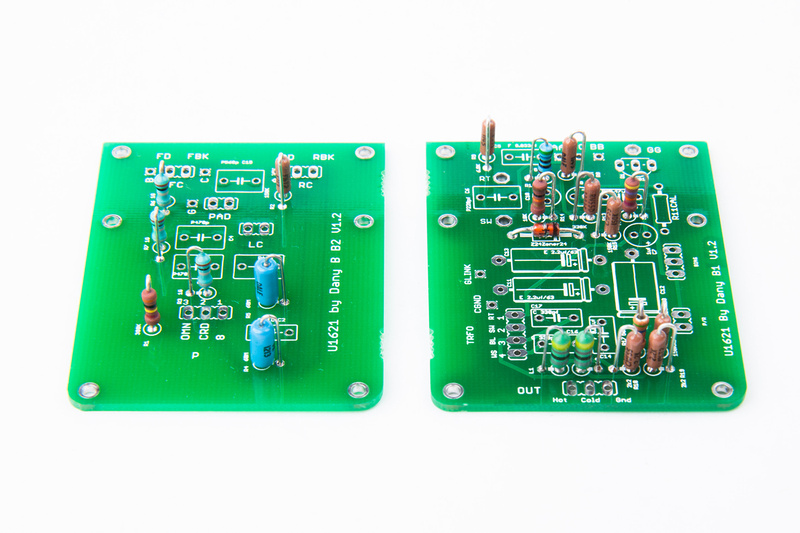
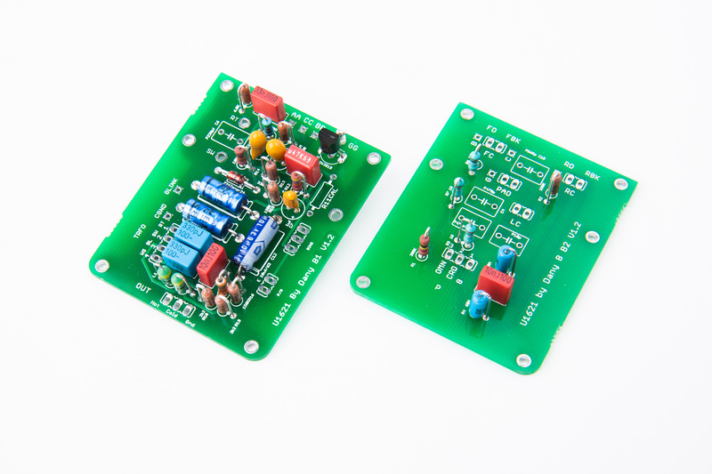
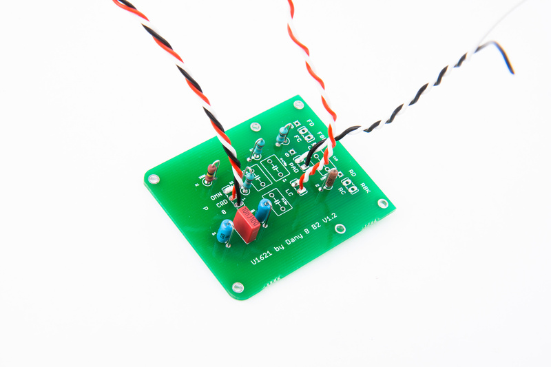
So, after all that, I finally get to the pcb's. Note, I changed bodies mid-stream on this project so we are now utilizing poctop's large version of the boards designed to fit ShuaiYin SYT-5 bodies.

p1289026986-5.jpg


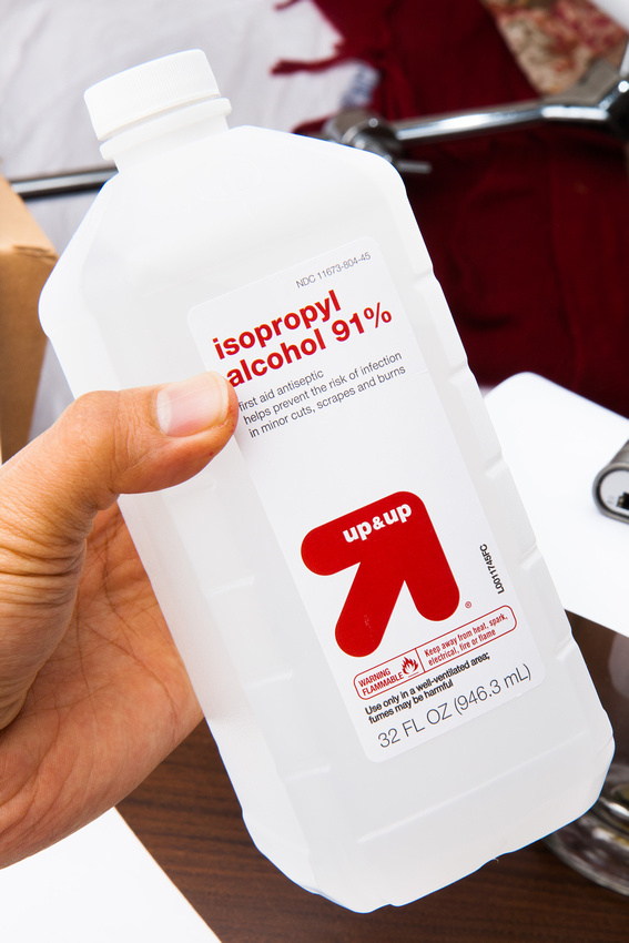
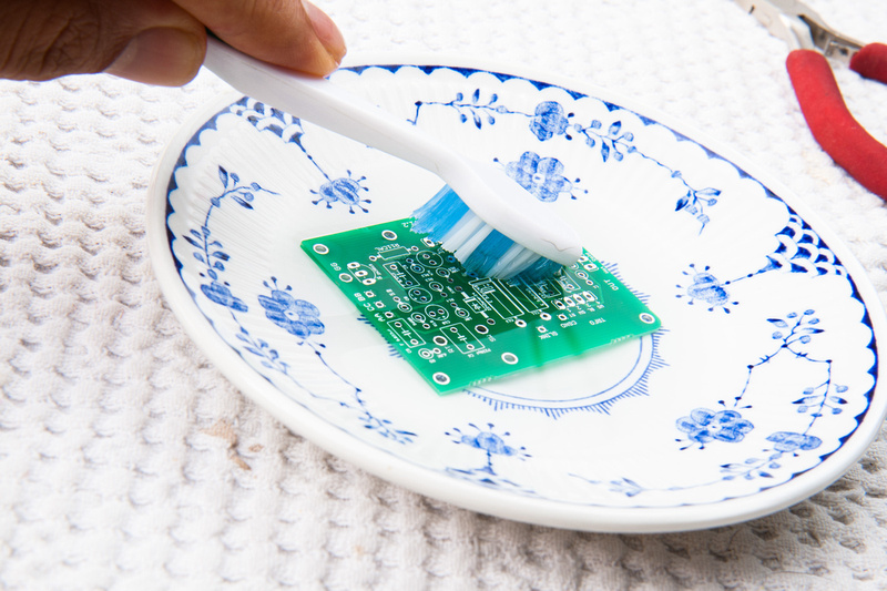
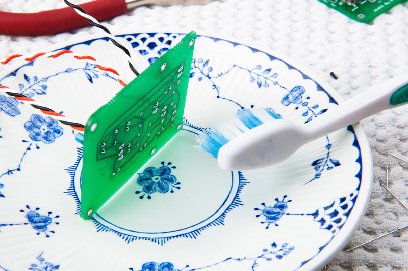
Since I started building mics, and read about high impedance sections of the circuit needing to be clean of solder flux, I've been super-obsessive about cleaning everything.  I found some 91% isopropyl alcohol at the convenience store and it's been working well for me in conjuction with a toothbrush.

p1289027680-5.jpg


The first of many dips into the cleaning solution.

p1289028294-4.jpg


I select one of my newly matched pairs of resistors and begin populating.

p1289028910-4.jpg


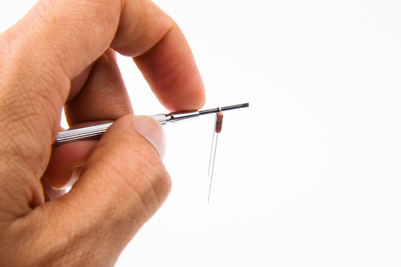
I use the smallest screwdriver shaft that I have to help bend the resistor leads nicely.

p1289029098-4.jpg


And, I start to populate referring to the BOM.  I did not sort all of my components onto a piece of paper like I usually do because all of my parts were still in their Mouser Electronic baggies and clearly labelled.

p1289030782-4.jpg


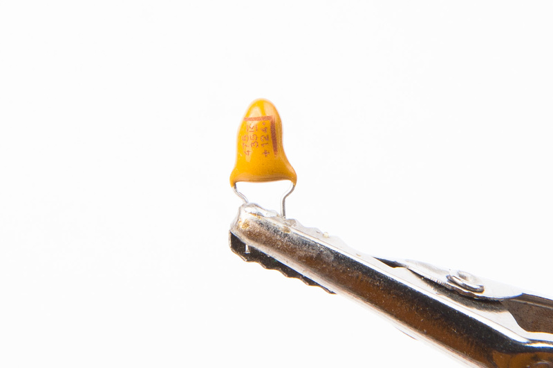
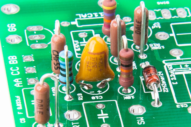
Next, I move to the capacitors.  The tantalum caps have polarity, so heed the markings even though they are small.  I am building per the "original" options on the BOM, so I will be using tantalum and polystyrene capacitors.

p1289031092-4.jpg


p1289031156-4.jpg


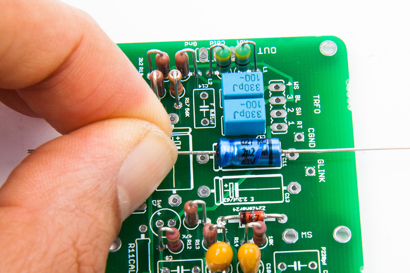
The electrolytics also have polarity, so make sure you get the "+" and "-" sides correct.

p1289031316-4.jpg


The teflon isolation pin is press-fit into the provided hole.

p1289031536-4.jpg


and, most items are populated with the exception of the polystyrene capacitors.  I read that those are sensitive to alcohol, so I wanted to clean the boards thoroughly before I install those.

p1289031736-4.jpg


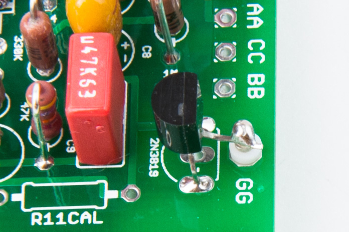
Note, the drain leg of the jfet is soldered to the teflon isloating pin and not to the through hole on the PCB.

p1289324188-4.jpg


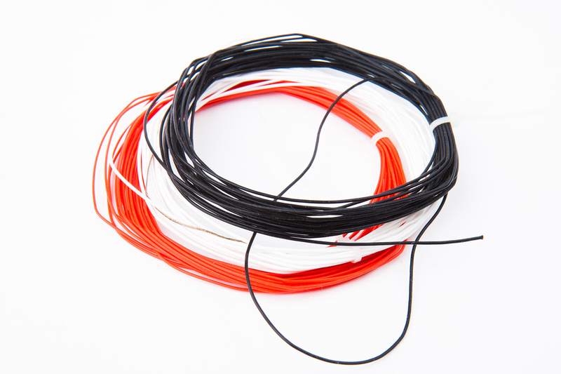
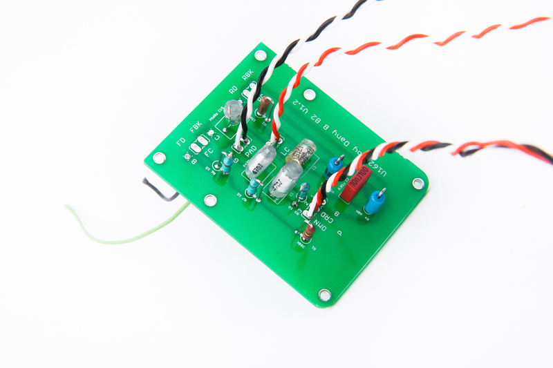
Next, I pull some 24 AWG silver teflon wire.

p1289032098-4.jpg


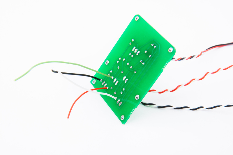
and connect my wires for switches (Low Cut, Pad, and Pattern).

p1289032456-4.jpg


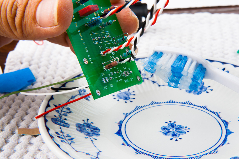
Before the Styrenes go in, I clean my PCB with alcohol and a toothbrush.

p1289032670-4.jpg


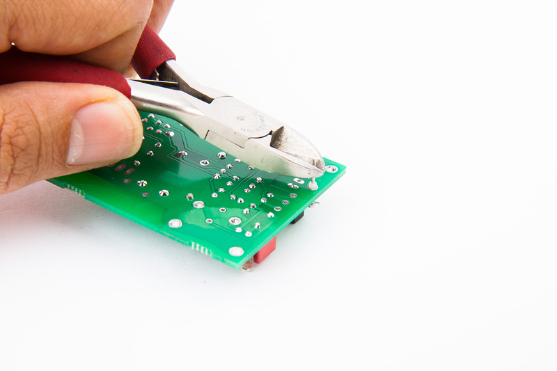
Next, I trim the pin of the teflon isolator so the PCB's will clear each other when mounted.

p1289033534-4.jpg


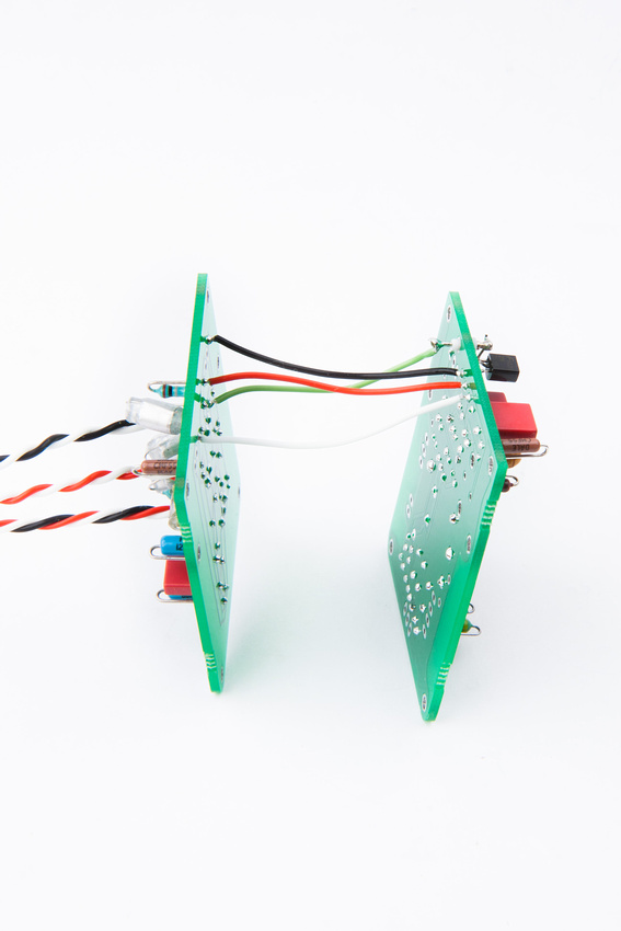
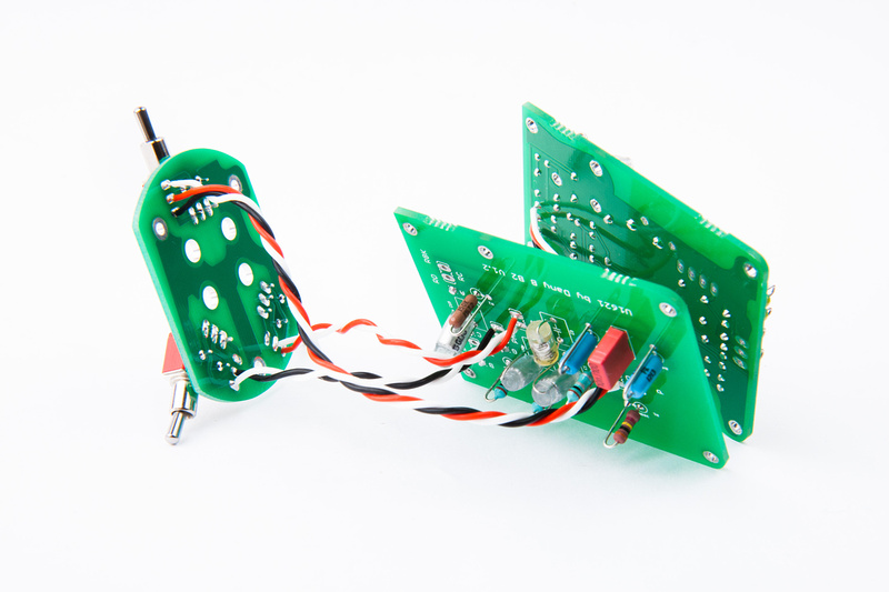
. . . and install jumper wires to connect the 2 pcb's together.

p1289033846-4.jpg


Every time I solder, I leave flux on the PCB, so I clean whenever possible.

p1289034116-4.jpg


And styrene capacitors are populated.

p1289034782-4.jpg


And, at this point, I complete the connections between the 2 pcb's.  A to AA, B to BB, C to CC, and G to GG.  Note, G attaches to the teflon isolated pin.

p1289035136-5.jpg


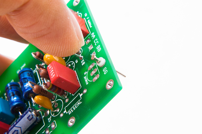
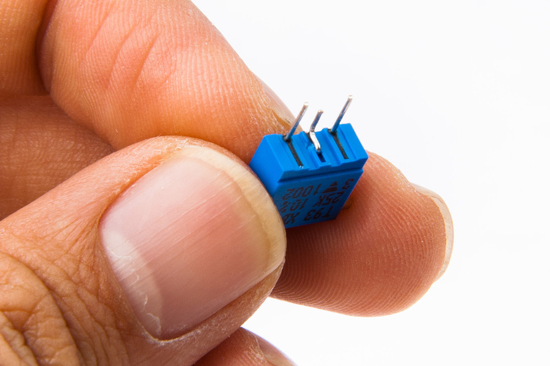
The large PCB leaves provision for separate installation of the bias potentiometer.  Unfortunately, the original BOM had a trim pot spec'd that had staggered leg configuration instead of straight like on the PCB.  I simply bend the center pin a little bit to fit the straight hole pattern.

p1289035268-4.jpg


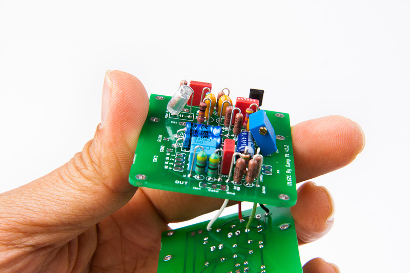
with such a large diamter microphone body, I doubt it will be a problem, but I install the trim pot at an angle to help with component clearance near the edge of the PCB.

p1289035478-4.jpg


And, at this point, I make a quick check just to see where everything will sit inside the microphone's frame rails.

p1289035940-4.jpg


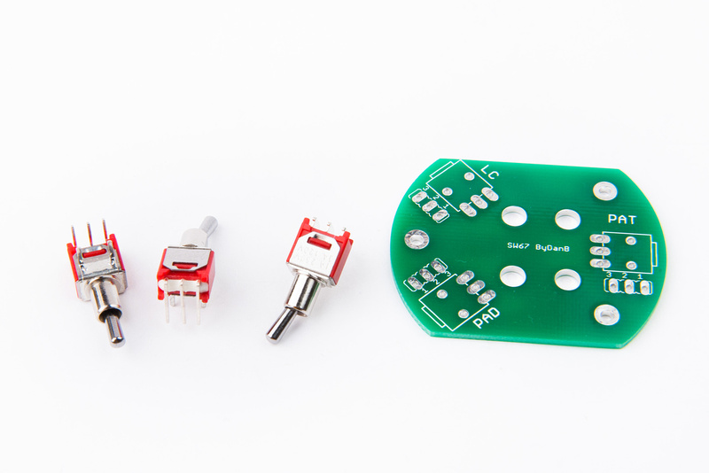
Next, I pull a switch mounting pcb which I have a supply of in stock from poctop as well as the 3 switches provided by the factory.  2 of the switchs are on-on type and one of them is on-off-on for the pattern adjustment.

p1289036376-4.jpg


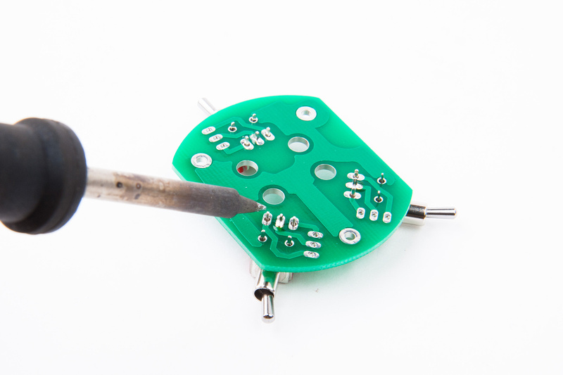
I solder a single pin on each of the switches to begin so I can make small adjustments and line them up perfectly with the screen printing on the front side.

p1289036592-4.jpg


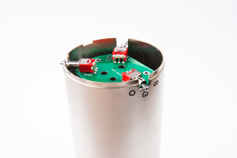
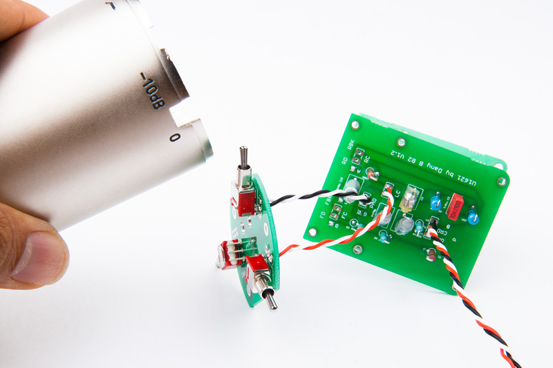
After confirming alignment, I solder the remaining legs and keep my microphone outer tube handy because I will refer to the screen print markings on the body to make sure I wire up the switches properly.

p1289065544-4.jpg


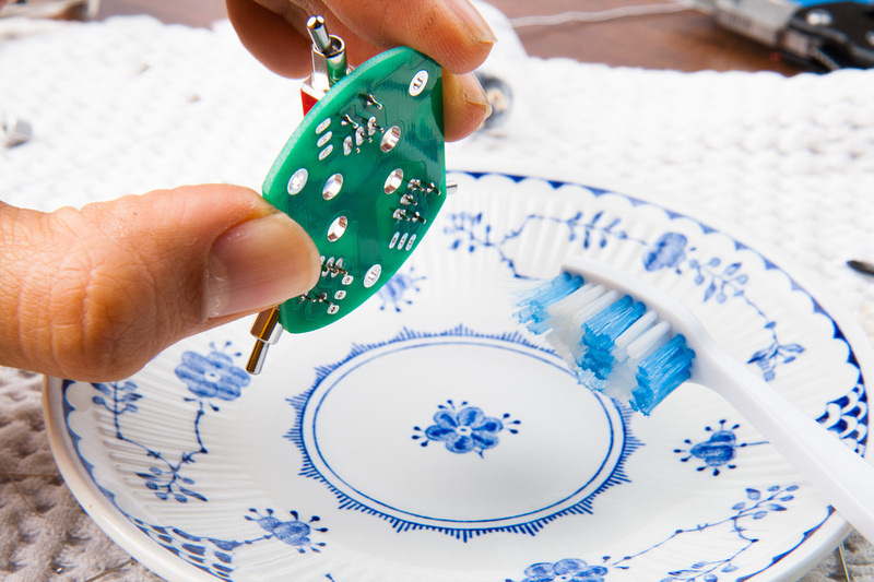
And, I take the opportunity to thoroughly scrub my switch PCB with alcohol.

p1289065854-4.jpg


And, I begin wiring the switches checking carefully to make sure my switching corresponds to the markings on my particular microphone body.

p1289066420-4.jpg


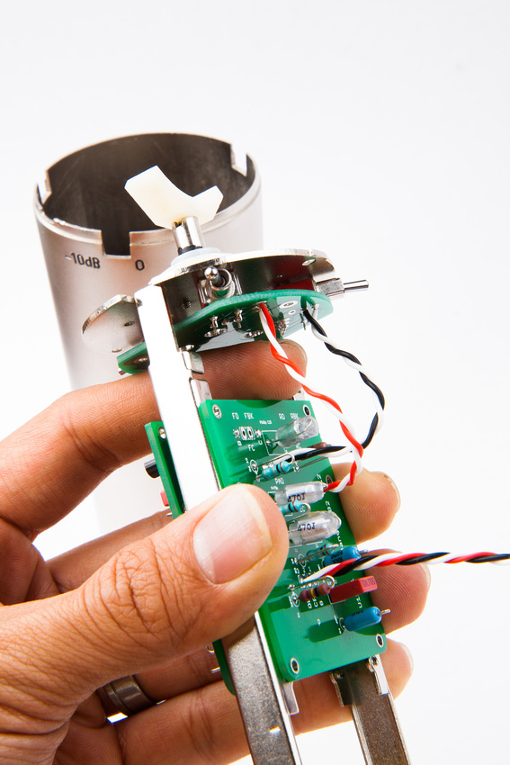
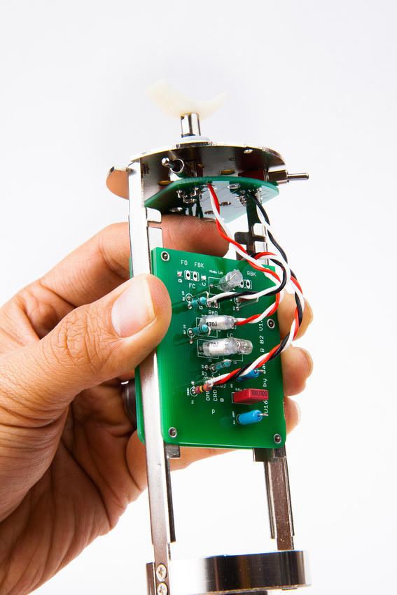
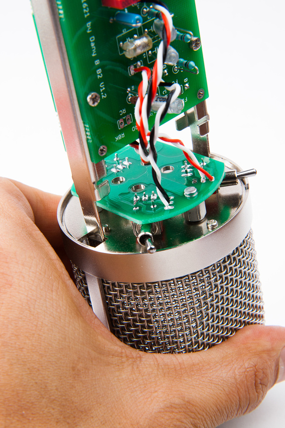
A quick test fit confirms my wire lengths are reasonable.  I want the runs to be relatively short, but also want to be able to move the boards a bit for diagnostics and repair in the future.

p1289066748-5.jpg


All 3 switches are now wired up.
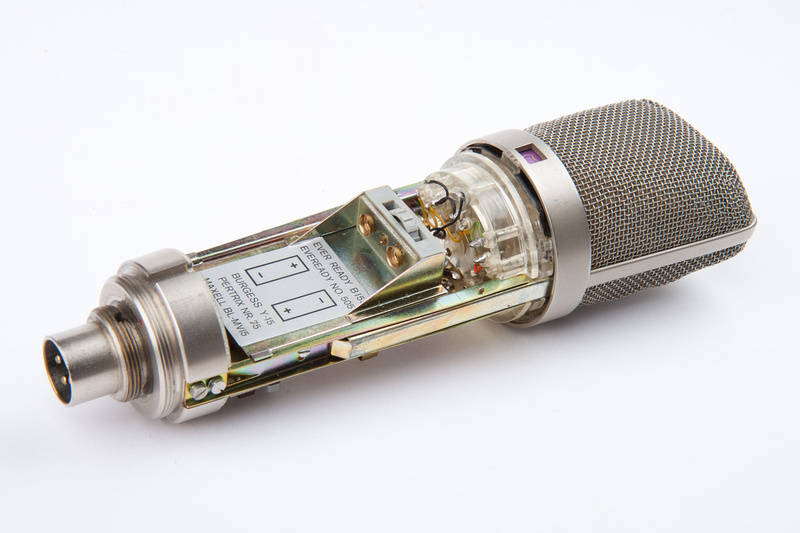
p1289067274-5.jpg


p1289067794-4.jpg


Looks great.
The SYT-5 looks like a much nicer body to work with than the BM-600; it was very tight getting it all in there. Might be in my best interest to pick up an SYT-5 while you still have some unspoken for.
 
kevinkace said:
Looks great.
The SYT-5 looks like a much nicer body to work with than the BM-600; it was very tight getting it all in there. Might be in my best interest to pick up an SYT-5 while you still have some unspoken for.

There was nothing really wrong with the BM600 body as I saw except the finish was painted instead of nickel plate.  I just wanted to trade tskguy for one of his capsules.  Unfortunately he delivered K67 instead of the isolated backplate ones that U87 needs.  So, since that has to go back to get fitted with isolated screws, I'm going to install one of the Peluso caps in this build.  No complaints about the Peluso capsule.  Matador just helped repair a vintage 1971 U87 in studio by replacing the worn capsule with a Peluso and it sounds fantastic.  We retained the stock capsule as-is because it still limps along barely and upon resale if that ever comes around, the original capsule will be preserved for the mic to hold value.
 
WWWWOOOOOWWWWW,  This is a real Pictorial, Thanks For doing this Chung , it is just pure Quality.
it seems nothing can go wrong in your build looking a those pictures :)
Keep up the good work,
all the best ,
Dan,  ;D
 
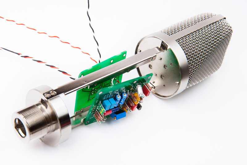
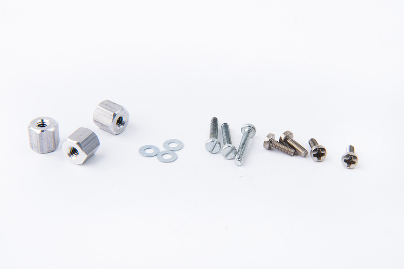
Next, I pull some hardware. . . these are 5mm and 12mm M2 screws, 1/4 inch 4/40 standoffs (these are not quite "proper" but are what I had), and some washers.

p1289852390-4.jpg


The 4 short M2 screws attach the PCB's to the frame rails.  I made sure to leave enough wire slack to be able to remove and work on each PCB if necessary to change components.

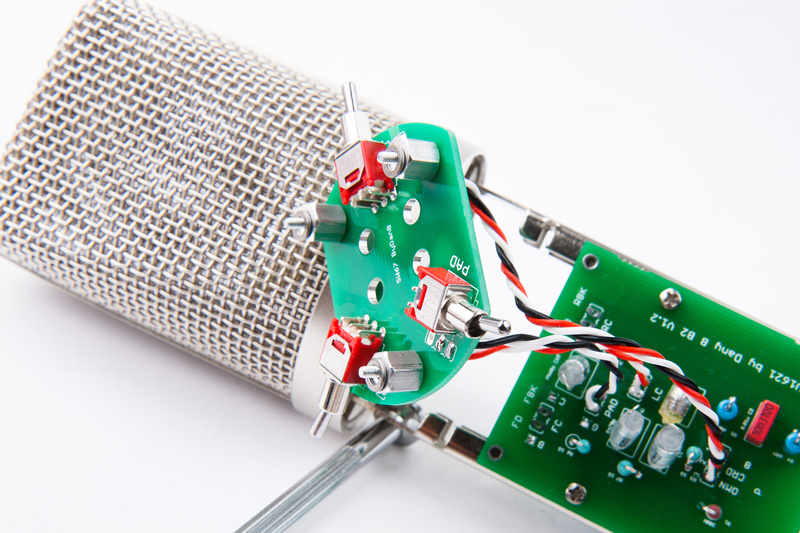
Washers and spacers go in to install the switch PCB.

p1289852486-4.jpg


p1289852846-5.jpg


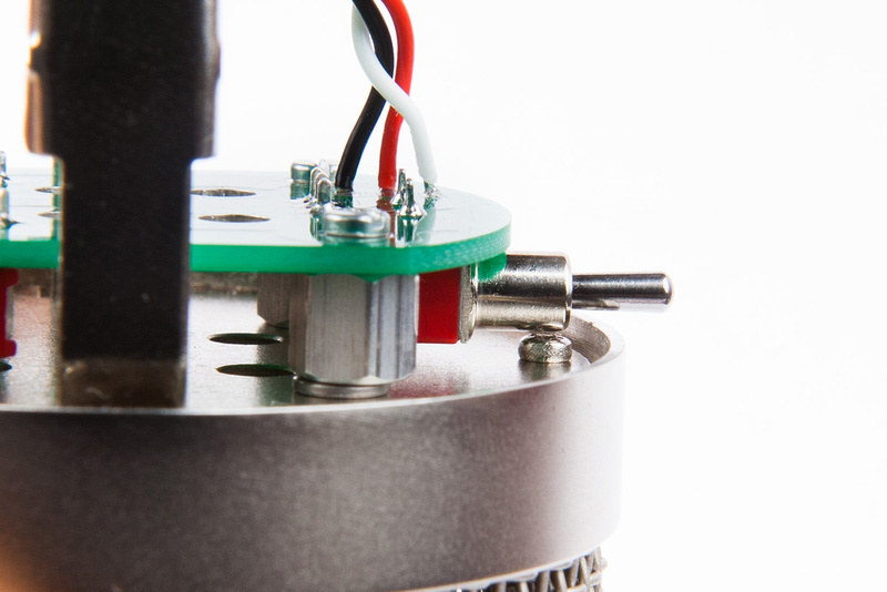
This body was not designed for 3 switches.  The reason I'm using washers is to make this screw clearance under the pattern switch (that was not in the mic's original oem layout).

p1289853274-4.jpg


Two solutions are possible here.  . . well, two easy ones and one harder one.  The easiest is the one depicted here which is add a washer to the 1/4" standoffs to clear the screw.  The second easiest is bevel the hole on the headbasket base plate and use a flat head washer in this position.  The third would be to drill 2 new holes to mount the headbasket that do not interfere with the switch and tap those holes.

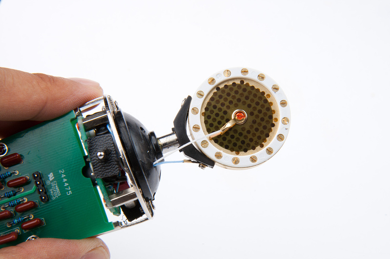
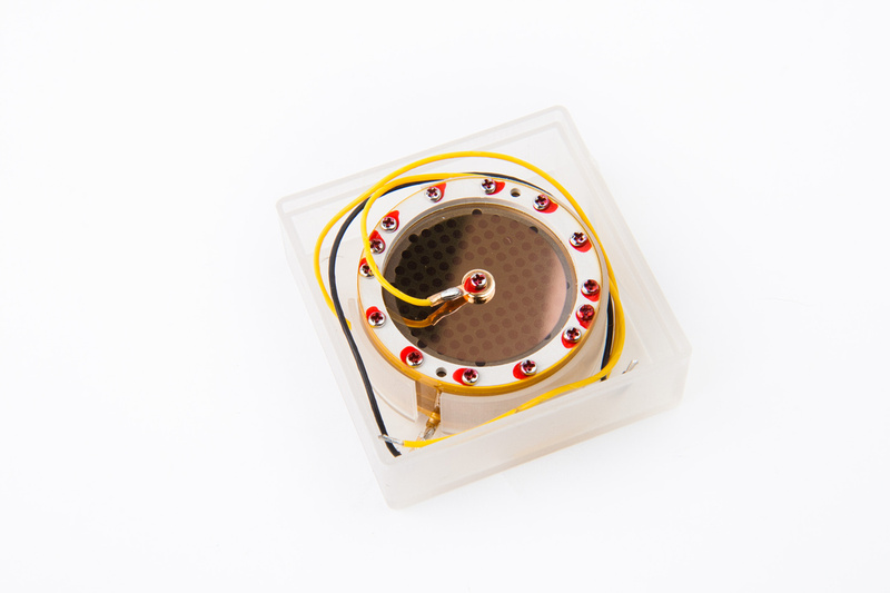
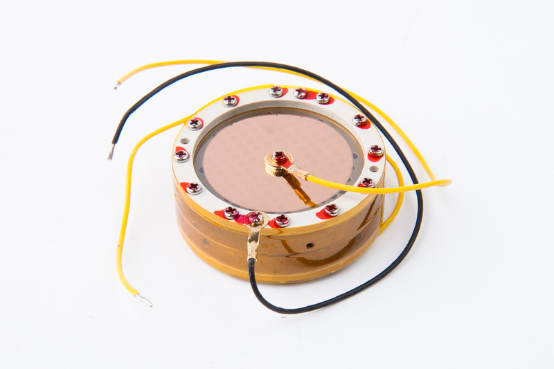
Earlier on, detailed photos were requested of the Peluso capsule, so here we go.

p1289853352-4.jpg


p1289853470-4.jpg


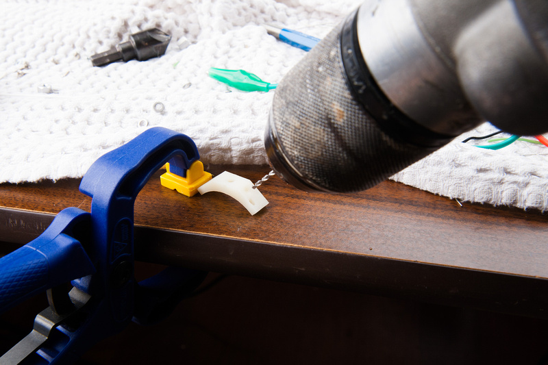
The capsule mount that is included with this mic body is designed for K67 installation so I need to drill one mount hole manually onto the capsule mount.

p1289853546-4.jpg


It's not the cleanest job because i had to enlarge the hole because I originally drilled it in the wrong spot.  Ugly, but it'll still work.

p1289853746-4.jpg


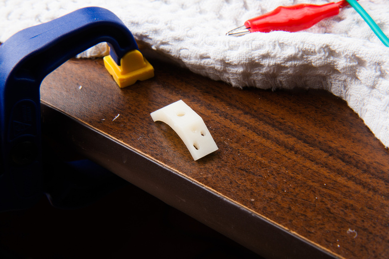
One note about the capsule mount, it does sit a bit low in the headbasket, but there is an easy solution.  The screw thread is M3, and a standard male to female M3 standoff at about 6mm length can be mounted under the capsule mount and put the capsule right where it needs to be higher in the headbasket.  Easy peasy.  I'll put one on my next order and demonstrate.

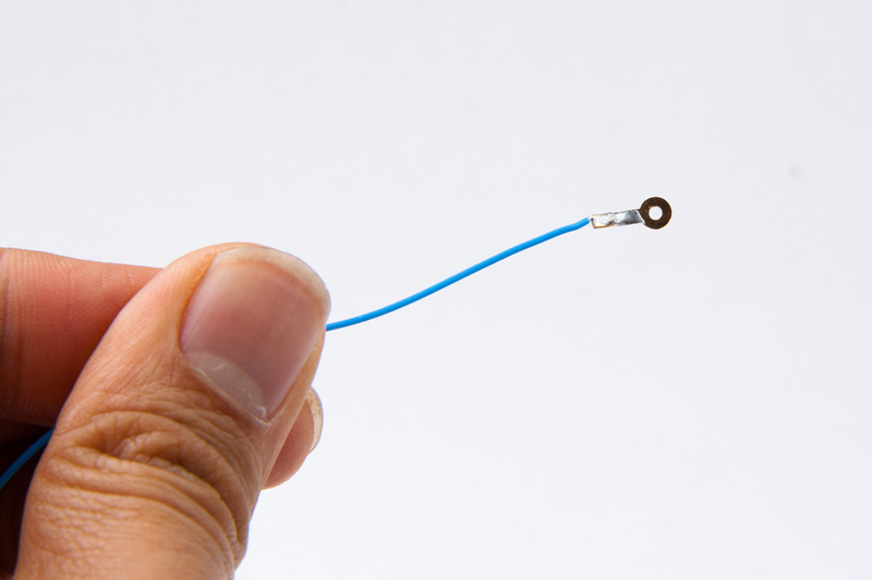
The Peluso capsule is supplied with wire tabs, screws, and washers.  I use 30awg silver teflon wire to make a backplane connector.

p1289854028-4.jpg


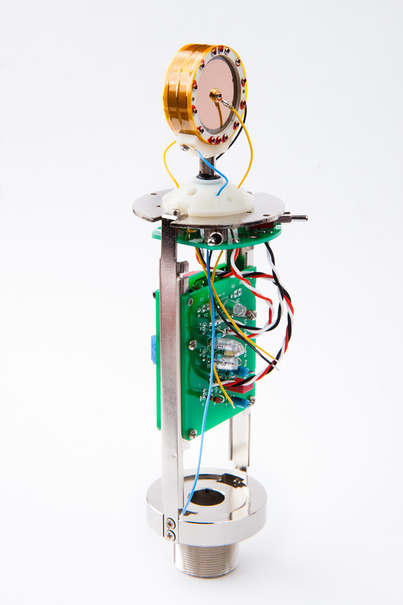
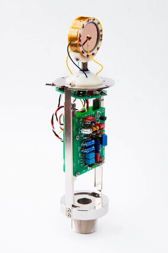
Next, I install the capsule and thread the wires through the nice pathways provided.  I quite like this capsule mount because the height can be easily adjusted and the base shape is curved.

p1289854112-5.jpg


p1289855878-5.jpg


chunger said:
on with the build. . . it was really nice that folks were able to find a documentation error in the ami t13 transformer lead colors recently and resolve the low output problem a lot of folks were experiencing. 

There is no documentation error. The error is that everyone is turning there transformers around and totally screwing up the impedances.

Since this is an original Non-"A" build you shouldn't be comparing the output level to the "A" circuit which in fact has a 10db hotter output than the original that your building here. The U87 transformer is a stepdown transformer, around 10:1. The output of the transformer should be 200 ohms (your ~22R DCR readings) as shown in the schematic and the AMI datasheet.

I can't tell from the documentation that's provided, but you should also bypass R20/R21 pad that was installed on the imported U87's per Gotham's spec for North American microphones.

Regards,
Mark
 
Back
Top