P2P Redd 47 - a few questions

GroupDIY Audio Forum

Help Support GroupDIY Audio Forum:

This site may earn a commission from merchant affiliate links, including eBay, Amazon, and others.
If one were to use a 1:10 Jensen input xfrmer what would  the zobel be?

For the zobel you could try different RC values using a square wave generator and an oscilloscope if you have them. The folks at Jensen might have a recommended circuit for the intended impedance of the transformer -- it doesn't hurt to ask. I'm not sure how the 1:10 ratio would effect the input - you might need to load the secondary to correct the reflected input impedance.

Yes; more correctly, it must be tied to the negative side of the smoothing cap, which happens, very often, to be tied with ground too. What I mean is, don't just return this center-tap to any old ground anywhere.

Okay this makes sense, but with the CT tied to ground, I'm unsure about how to rectify the 45V bias tap for use in the 48V DC supply.
 

Attachments

  • 45V_tap.gif
    45V_tap.gif
    24.6 KB · Views: 119
seavote said:
was hoping you guys would get around to this.  but i contacted guitarmaker he is ok with me sharing his layout. he also has a layout for the PSU he used but a lot of members used a modded gyraf G9 PSU.  as for 48V  phantom,phase etc id use this:
http://www.jlmaudio.com/shop/index.php?_a=viewProd&productId=8

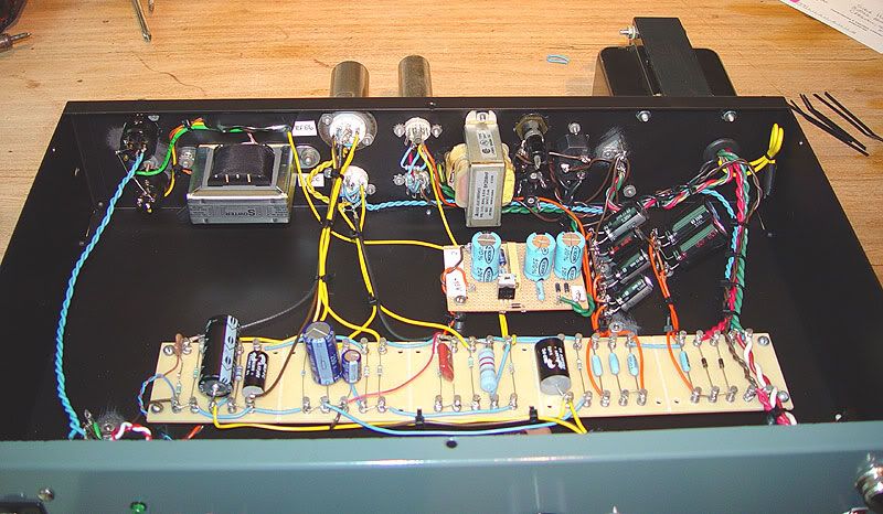
reddamplayout.jpg


reddpowerlayout.jpg


redpic1.jpg

Hey I have a question.

<---- newb

that board that you used to connect all of your caps and resistors.. Where did you get it? How much was it? How did you make your holes for your tubes? Where do I get tube sockets?

I need to step my game up and build some big boy tube pres.
 
that board that you used to connect all of your caps and resistors.. Where did you get it? How much was it?

The board in the front is a turret board -- probably the Keystone 2" scored model. You can get them at Mouser (534-15033) or other electronics suppliers. The board in the back is perfboard.

How did you make your holes for your tubes?
Drill and then use a knockout punch. Greenlee makes good ones. Mouser sells them too.

Where do I get tube sockets?
Tube Depot has a nice variety.
 
I think I've found the answer to my questions about rectifying the bias tap for phantom power. Thanks to Letterbeacon and Ruffrecords for working this out on another post! http://www.groupdiy.com/index.php?topic=42745.40

Ruffrecords had this to say about grounding...
I would recommend you connect the (common) HT and Phantom zero volts to the chassis right near the the mic input XLR. From this same (star) point, take a lead and connect it direct to the mains earth pin on your mains input connector.

Letterbeacon - if you're still reading, please let me know how this worked for you!
 

Attachments

  • phantom psu half wave.JPG
    phantom psu half wave.JPG
    24.7 KB · Views: 135
Hi earthsled,

Unfortunately I haven't got round to hooking this up yet, and when I do, it looks like I'm going to stick another mini transformer in there to supply the 50VAC as I've already bought Ian's phantom PCB.  I designed a stripboard layout for the ammended half wave circuit, but that's as far as I got I'm afraid!
 
Thanks for the info letterbeacon. I'm going to give the 48V half-wave circuit a try with my build. We'll see how it goes.

Considering the DC heater supply again, I thought it might be best to double Mogan Jones' circuit after regulation in an effort to reduce the watts/heat dissipated by the regulators. This way the current draw would be split between the two channels. Please let me know if anyone sees issues with this setup.

Thanks!
 

Attachments

  • 6.3V PSU v2.gif
    6.3V PSU v2.gif
    110.5 KB · Views: 138
earthsled said:
Considering the DC heater supply again, I thought it might be best to double Mogan Jones' circuit after regulation in an effort to reduce the watts/heat dissipated by the regulators.
Far be it for me to question a true tube guru like Morgan Jones but it seems to me that instead of using Supa fast Schottkys & zillion uF on the input to the regulators, a small resistor in series before the capacitor would reduce the ripple frequencies and give the LM317s an easier job too.  Cheapo 1n400x would be better too.

Load Regulation would be poorer but valve heaters are hardly a fast changing load like a Class B amp.

Comments from our tube gurus?
 
i had a terrible time with regulators breaking one by one after about a year of operation.

to much inrush current,

you can just use a bullet proof pi filter.

use a huge bridge, like a 30 amp heat sinkable type,

then buy a 10 amp choke coil,

get some computer caps, and you will have quiet heaters and the circuit will never break.

by the time you figure out that you need a pass transistor, and slow ramp up, and maybe a surge resistor, and a bigger chassis, you could have been done with the simple circuit.

another problem with regs is that sometimes the heaters look like a short, so they shut down and stay there. you have to toggle the pwr switch to get the tubes started, this will break the switch fairly quickly and leave you with more heartburn, :-[
 
Thanks for your comments!

All things being equal, I trust that Morgan Jones' original design is a good one. For my purposes, it is a good starting place.

I'm mostly curious if a linear power supply like this one can be "split" after rectification so that the current draw is divided between two regulators and the accompanying circuitry. Is this safe to do, or will it cause issues?
 
earthsled said:
I'm mostly curious if a linear power supply like this one can be "split" after rectification so that the current draw is divided between two regulators and the accompanying circuitry. Is this safe to do, or will it cause issues?
No particular issues.
 
Far be it for me to question a true tube guru like Morgan Jones but it seems to me that instead of using Supa fast Schottkys & zillion uF on the input to the regulators, a small resistor in series before the capacitor would reduce the ripple frequencies and give the LM317s an easier job too.

What resistance would you suggest? Something like 100R would need to be 225W for the specified 1.5A current draw, right?

Cheapo 1n400x would be better too.

I'm not sure if the 1N400* would tolerate the current. MJ suggests individual 3A 1N54** rectifiers, or a 4A bridge rectifier package as alternatives to the Schottkys. The 1N5400s would be cheaper, but about the same size as the Schottkys.

As for caps, I plan to use 2x 4700uF 35V. These seem to be relatively inexpensive, compact, and readily available.
 
earthsled said:
What resistance would you suggest? Something like 100R would need to be 225W for the specified 1.5A current draw, right?

In this case we're only interested in dropping some 1-3V. If at all. Let's say 0.5-2ohms, but it really depends on what you start with. The regulator needs about 3V to work. It means the voltage in the regulator input should be 9.3V minimum.

As for diodes, check mouser or digikey for the cheapest bridge rectifier chip in the range of 100-600V, and something like 3-10A. It's really non-critical and they are all roughly the same price and physical size that bolt onto chassis.

You're possibly over-thinking heaters a bit, actually a lot seeing that dual set up. I've certainly done that in a few past projects, but learned from it. Bridge rect and CRC is really all you need, perhaps CRCRC if you want to go real fancy. Enter regulator into the equation and it's actually less failure proof already, with no measurable difference in noise, depending somewhat on what voltage you start with. And better make sure that regu won't overheat! Depending on case internal conditions for example in a rack full of gear even your dual regulator set up might flip into thermal protection mode.

These light bulbs tolerate quite the range of under or over heating anyway, in case your wall power fluctuates. Go passive.

[edit]

As a sidenote, I don't know what kind of legacy projects people here want, but a word of advice:

These strictly regulated very stiff G9 style B+ lines and heaters will not give you the redd47 sound like your grandma used to make. PSU's do actually affect the way tube preamps sound, and a more simple passive PSU will probably land you significantly closer to that "legacy sound". Heaters admittedly don't really change anything except possibly hum but B+ lines are much more interactive than one might think.
 
earthsled said:
Cheapo 1n400x would be better too.
I'm not sure if the 1N400* would tolerate the current. MJ suggests individual 3A 1N54** rectifiers, or a 4A bridge rectifier package as alternatives to the Schottkys. The 1N5400s would be cheaper, but about the same size as the Schottkys.
Mea maxima culpa.  My excuse is kunt reed en rite.  :-[
As for caps, I plan to use 2x 4700uF 35V. These seem to be relatively inexpensive, compact, and readily available.
Did Morgan Jones actually specify the Schottky's and zillion uF caps?
 
ps2.png


Newbie having a problem getting 380v 30mA for the connection to the Redd 47 power section.  Here is what I got so far.  After the rectifier I am getting about 400v so I understand need about 20v dropped, but how do I drop the 50mA to 30mA.  The R1 is 1k 5watts and R2 is the 470K 1watt bleeder resistor shown in the original schematic.  R1 is getting quite hot so I assume I need to somehow drop 20mA as well.  Sorry for the stupid questions,  I am trying to understand but my skull is thick.  ChrisP
 
chrispsound said:
Newbie having a problem getting 380v 30mA for the connection to the Redd 47 power section.  Here is what I got so far.  After the rectifier I am getting about 400v so I understand need about 20v dropped, but how do I drop the 50mA to 30mA.
One drops volts, not milliamps. You need to drop 20V, the current drawn for one REDD47 is 20mA, so the resistor needs to be 20/20m => 1k. The dissipation is 20x20m => 400mW, so the resistor should not be very hot. Now if the current is higher than 20mA, the resistor must be modified accordingly. If R1 is getting very hot, check the voltage at the output, there may be too much current drawn.
 
Newbie having a problem getting 380v 30mA for the connection to the Redd 47 power section.  Here is what I got so far.  After the rectifier I am getting about 400v so I understand need about 20v dropped, but how do I drop the 50mA to 30mA.  The R1 is 1k 5watts and R2 is the 470K 1watt bleeder resistor shown in the original schematic.  R1 is getting quite hot so I assume I need to somehow drop 20mA as well.  Sorry for the stupid questions,  I am trying to understand but my skull is thick.  ChrisP

These are good questions - and important ones!!  :)

What is your power transformer's voltage rating on the secondary? If it's close to 540V, then you can use a power supply similar to the original spec.

Let's compare your schematic to the attached image...

C1 is substituting for C12B and C
R1 is substituting for R20
C2 is substituting for C12A (47uF is high, 22uF would be closer)
?? is substituting for R19
?? is substituting for C9, 10, 11 (you can use a single 33uF here)
?? is substituting for R18
?? is substituting for V3, V4 (you can use zeners here if you like)
R2 is substituting for R16

R22 is optional, and R17 isn't needed if you use zeners

All this to say, with the addition of the 2 extra 1K resistors, your 470K will get less hot and you should be closer in voltage.
 

Attachments

  • redd_psu.gif
    redd_psu.gif
    18.4 KB · Views: 110
chrispsound said:
ps2.png


Newbie having a problem getting 380v 30mA for the connection to the Redd 47 power section.  Here is what I got so far.  After the rectifier I am getting about 400v so I understand need about 20v dropped, but how do I drop the 50mA to 30mA.  The R1 is 1k 5watts and R2 is the 470K 1watt bleeder resistor shown in the original schematic.  R1 is getting quite hot so I assume I need to somehow drop 20mA as well.  Sorry for the stupid questions,  I am trying to understand but my skull is thick.  ChrisP


Adding to what the others have said, the 50ma figure for the PT is assumed to be it's current rating.  This is simply a figure that let's you know how much current you can safely draw at a given voltage.  It's a figure of capacity.  The circuit will only draw the current it's designed for.  Some helpful basics to remember here is that current will be the same in a series circuit, only voltage drops.

I've found that resistors dissipating around 1W or so will often get warm after a while but as abbey road said, you're well within safety spec with a 5W part.  The PT will also get a little warm after a bit at that current draw, but you're still under 50%, so - ok.
 
earthsled said:
Newbie having a problem getting 380v 30mA for the connection to the Redd 47 power section.  Here is what I got so far.  After the rectifier I am getting about 400v so I understand need about 20v dropped, but how do I drop the 50mA to 30mA.  The R1 is 1k 5watts and R2 is the 470K 1watt bleeder resistor shown in the original schematic.  R1 is getting quite hot so I assume I need to somehow drop 20mA as well.  Sorry for the stupid questions,  I am trying to understand but my skull is thick.  ChrisP

These are good questions - and important ones!!  :)

What is your power transformer's voltage rating on the secondary? If it's close to 540V, then you can use a power supply similar to the original spec.

Let's compare your schematic to the attached image...

C1 is substituting for C12B and C
R1 is substituting for R20
C2 is substituting for C12A (47uF is high, 22uF would be closer)
?? is substituting for R19
?? is substituting for C9, 10, 11 (you can use a single 33uF here)
?? is substituting for R18
?? is substituting for V3, V4 (you can use zeners here if you like)
R2 is substituting for R16

R22 is optional, and R17 isn't needed if you use zeners

All this to say, with the addition of the 2 extra 1K resistors, your 470K will get less hot and you should be closer in voltage.
earthsled, my schematic is for the power transfomer and rectifier(with extra filtering) to be added to the Redd 47 not to replace the filtering/ regulating section of the Redd 47.  My Power transformer(Analog Metric t30L torroid) secondary is marked 280Vac 50mA it and Vac  reads a little higher unloaded with my fluke meter.  I am getting 45mA before the 8.2K plate resistor so then my circuit must be drawing too much current and that is what is making my 1K 5watt and 8.2K resistor get way hot.  What would cause this(other than me buggering something durind assembly).
abbey road d enfer said:
chrispsound said:
Newbie having a problem getting 380v 30mA for the connection to the Redd 47 power section.  Here is what I got so far.  After the rectifier I am getting about 400v so I understand need about 20v dropped, but how do I drop the 50mA to 30mA.
One drops volts, not milliamps. You need to drop 20V, the current drawn for one REDD47 is 20mA, so the resistor needs to be 20/20m => 1k. The dissipation is 20x20m => 400mW, so the resistor should not be very hot. Now if the current is higher than 20mA, the resistor must be modified accordingly. If R1 is getting very hot, check the voltage at the output, there may be too much current drawn.
the current is higher than 20mA so how should the resistor be modified?  Thanks for all your posts.  ChrisP
 
Back
Top