You are using an out of date browser. It may not display this or other websites correctly.
You should upgrade or use an alternative browser.
You should upgrade or use an alternative browser.
stay at home type 69 project
- Thread starter dogears
- Start date


Help Support GroupDIY Audio Forum:
This site may earn a commission from merchant affiliate
links, including eBay, Amazon, and others.

Ok so on this 4th I must have made a blunder somewhere or a part is defective. Just q5 q6 q7 measure too high in general on all pins while q8 and q10 are fine. Just looking at q5 base on a working card you get 0.96v while I’m seeing over 6v and the rails measure fine. Not sure how to approach troubleshooting other than reflowing the solder which I did. The transistor are the correct orientation and type. Would the first step by to change out all 3? Is this more likely to be a defective component ?
And alas just adding this in as well. I just wired a card that was measuring fine on the transistors and it is working as I thought however the eq section has no gain. Could someone point me where to look?
And alas just adding this in as well. I just wired a card that was measuring fine on the transistors and it is working as I thought however the eq section has no gain. Could someone point me where to look?
Last edited:
Q6 and Q7 definitely shorted for some reason. After replacing I am getting amplification but still have some intermittent stuff when using the switches. Besides solder points is there anything else that may be expected to short with q6 and q7?

TwentyTrees
Well-known member
Looking great, congratulations!
Hey guys. Please help me troubleshoot. I need to plug one module into the rack using extension cable to fix an issue with the phantom power. One cable had come off the switch. No big deal except there must have been a tiny piece of metal inside the connector of the extension cable cause upon startup I blew 2 electrolytics. I later measured the voltages on the connector after removing and in fact they’re 64v on one of the tabs. Must have reversed polarity.
Anyway I replaced nearly all the 33uf electrolytics anyway and whatever electrolytic is left in the module seems to be measuring ok capacitance wise. There is both an audible noise coming from the card when powered and and a high oscillation coming from the speaker when plugged in.
The transistors all measure fine. Normal resistance on the transformer windings. Keep replacing electrolytics or look elsewhere ? Could the regulator be damaged despite -8v output ?
Last edited:
fritzmyname
Well-known member
")
Hi - just curious if you have specs/dimensions for your L-bracket?
I think you mentioned that it wound up being too long to use? Was the end of the bracket hitting the edge connector?
fritzmyname
Well-known member
Hi - just curious if you have specs/dimensions for your L-bracket?
I think you mentioned that it wound up being too long to use? Was the end of the bracket hitting the edge connector?
Hey, yeah you don't really need the L-bracket, I left it out.
The problem was, that the 2 screw holes on the pcb near the card edge connector are too close to the edge of the L-bracket (meaning the L-bracket should be longer or the 2 holes nearer to the center of the card). Save yourself the money and leave it out, the front panel alone is just fine for support!
Thank you @fritzmyname !
I'm making some mods that will result in having to wire all the pots and switches w/ leads rather than to the PCB, so I'll need to use a bracket of some sort to stick is all together.
I appreciate the info on the rear holes - it'll probably (hopefully?) be sturdy enough to just mount via the two in the front. Did you send Frank precise dimensions or was he working off of the gerber files/PDF?
Oh, also - if you wouldn't mind sharing your front panel files again that would be really kind - the link seems to be down.
fritzmyname
Well-known member
Ah I see
I just sent him the frontpanel design and told him to do an accompanying L-Bracket (assuming that the length of those is standard and thus there would be enough space for the rear holes…)
Those 4 holes would have been done by me regardless as he didn’t want to „guess“ the location.
I just sent him the frontpanel design and told him to do an accompanying L-Bracket (assuming that the length of those is standard and thus there would be enough space for the rear holes…)
Those 4 holes would have been done by me regardless as he didn’t want to „guess“ the location.
OK! Per @TwentyTrees very reasonable suggestion in a different thread, I'm planning on modding @dogears H9MR board to drop the EQ section and just build a two-stage preamp with a 10K TRIM pot in between the two 2128s.
I have the boards in hand, and I'm just tracing things out to figure out the best way to skip the EQ. Per the schem:
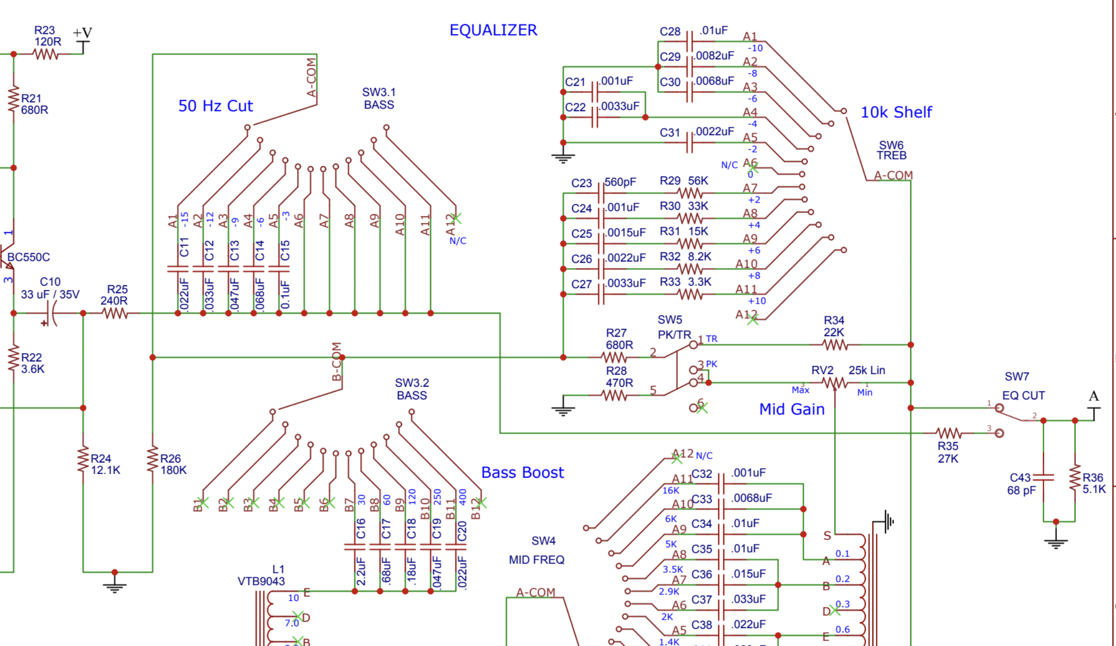
Would it make sense to jumper R25 and R35, and then run TRIM-3 to "eq cut 3", TRIM-2 to anything in the "eq cut 2 / C43 / R36" net, and TRIM-1 to the other side of R36 / GND?
I have the boards in hand, and I'm just tracing things out to figure out the best way to skip the EQ. Per the schem:
Would it make sense to jumper R25 and R35, and then run TRIM-3 to "eq cut 3", TRIM-2 to anything in the "eq cut 2 / C43 / R36" net, and TRIM-1 to the other side of R36 / GND?
TwentyTrees
Well-known member
Other way round - you basically want to preserve the "EQ out" signal path, which is R25, R35, C43 and R36. You need the voltage divider to preserve the gain structure* of the preamp (the second amp makes up for the loss in the passive EQ). Don't populate any of the EQ filter sections, and jump SW7.

That way you leave yourself the option of fitting the EQ at a later date if you decide to. It's a really nice EQ, clear but characterful at the same time.
* Replacing R36 with your 10k trim pot would give you an additional 4.5dB or so of gain at max setting, with full attenuation the other way.
I suspect you might run up against headroom limitations with increasing overall gain, but would be interested in your results if you do go down that road.
Last edited:
Ah - I see what you're saying. I was thinking of swapping out the R35/R36 voltage divider entirely with a 10K pot (this is per a suggestion ruffrecords/ian made in a different thread, but I suppose I could replace R36 with a 5K pot and have it be 'stock' at max cw and then full atten at max ccw.
Also curious - what is R25 doing?
I ordered extra PCBs to do the full project at a later date, just cost and my immediate need for some extra preamp channels has me looking at a budget/preamp-only version in the short term.
Also curious - what is R25 doing?
I ordered extra PCBs to do the full project at a later date, just cost and my immediate need for some extra preamp channels has me looking at a budget/preamp-only version in the short term.
Last edited:
what TwentyTrees says seems right to me. Omit the EQ switches, inductors, caps, and pots. Short R25 and R35, omit C43, and use SW7 and R36 as your pot wiring point. Top of travel at SW7-3, wiper at SW7-2, and bottom of travel at bottom of R36 / com.
I'd also start with R43 omitted. This is the gain set resistor in the second 2128 amplifier. When it is omitted, you get a unity gain follower.
I'd also start with R43 omitted. This is the gain set resistor in the second 2128 amplifier. When it is omitted, you get a unity gain follower.
Similar threads
- Replies
- 11
- Views
- 6K
- Replies
- 1
- Views
- 2K