Generic Grounding scheme--Could Someone Please Check This?

GroupDIY Audio Forum

Help Support GroupDIY Audio Forum:

This site may earn a commission from merchant affiliate links, including eBay, Amazon, and others.

donnysparks

Well-known member
Joined
Apr 14, 2005
Messages
129
Location
Birmingham, AL
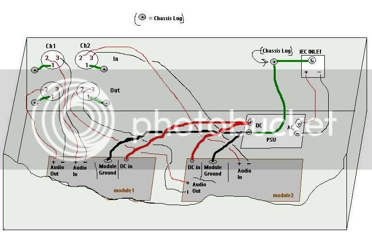
ok, moron question. i drew a quick sketch on microsoft paint to see if i follow the most recent thread on grounding. does this make sense for basic wiring of a stereo unit?


Sorry, don't know how to attach images directly to a post:
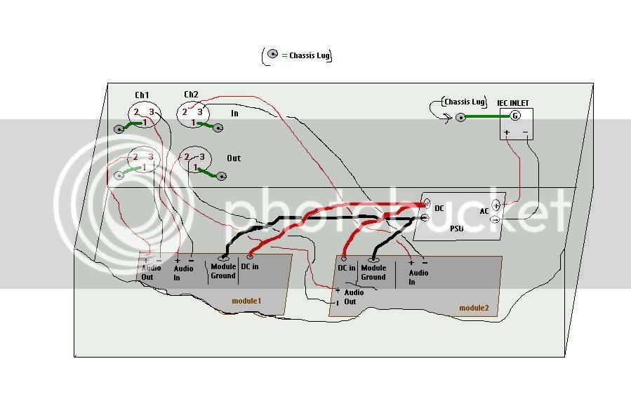
wiringscheme.jpg


also here: http://www.geocities.com/bud_deholly/wiringscheme.JPG


thanks in advance for any advice.
_________________
 
It looks fine except that you missed to reference the PSU to chassis.

I usually build a star ground where I attach the PSU ground and (in your case) the two PCB grounds. But the way you showed it (with the added PSU ground) should work fine as well.

Samuel
 
[quote author="Samuel Groner"]It looks fine except that you missed to reference the PSU to chassis.

I usually build a star ground where I attach the PSU ground and (in your case) the two PCB grounds. But the way you showed it (with the added PSU ground) should work fine as well.

Samuel[/quote]

thanks very much samuel. are you saying there should be a connection from the (-) terminal of the DC side of the PSU to the chassis ground lug? or from any part of the PSU (like one of the mounting bolts) to the chassis lug? for the latter, isn't the psu already referenced to ground by being mounted to the chassis?

also, the way you mention that you do it, would you just leave the negative terminal of the DC side of the PSU open and instead connect the PCB grounds and PSU to one point on the chassis?
 
[quote author="Mendelt"]Won't you get ground loops this way when you use unbalanced to balanced cables with pin 1 and 3 connected?[/quote]

Yes. The grouding sheme isn't optimal.
The audio ground should be connected to the chassis only at one point (thru a "ground lift" switch, IMO).

Regards,
Milan
 
I was drawing this with a single pole psu in mind. i also was assuming for this that the modules had a connection for ground (as a dedicated pin on the connector or similar). so in the case of a single pole supply, the ground connection from the modules would carry the ground plus carry the dc back to the psu, correct?

also, milan, when you say "audio grounds" do you mean all the pin 1's or the ground pins coming from the modules? doesn't the DC coming FROM the module need to go back to the power supply to make a complete circuit?

please excuse my ignorance. i obviously don't have a firm grasp on this stuff. i appreciate the help very much!
 
[quote author="donnysparks"]...the ground connection from the modules would carry the ground plus carry the dc back to the psu, correct?... [/quote]

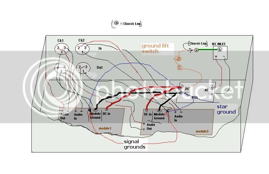
Yes. But, it's better if the signal ground and power ground-return are separated.
... when you say "audio grounds" do you mean all the pin 1's or the ground pins coming from the modules? ...

Yes, as shown in the picture below. If the signal and power ground aren't separated, omit blue wires and use thick wires for the power ground returns.

Regards,
Milan

grounds.jpg
 
this is my "standard" grounding scheme ( i'll try and use words rather than draw a picture ) and it is similar to your last picture.

all pin 1's from input and output XLRs go directly to the 0V point on their respective pcbs.
the mains socket earth pin gets tied directly to the chassis.

then at the PSU i connect 0V to the chassis via a 10R resistor with a 0.1uF cap in parallel across it. This "soft" grounds the mains / chassis earth with the signal "earth".

99% of the time this arrangement works well with no grounding / hum loop issues.
 
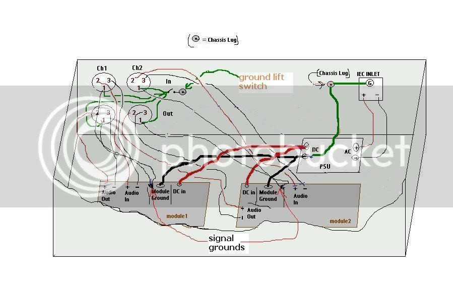
taking from all the suggestions thus far...

grounds2.jpg


eh? eh?

after reading the rane note on grounding i feel naughty connecting pin 1's to anything but directly to chassis. but it has been unanimous so far to the contrary.

squib, can you use a ground tab for 0V? all the modules i've worked with so far only have ground tabs. no separate pins for signal ground, power ground, etc.

thank you everybody for your help so far.
 
yes the rane note is very instructive.
Problem is that if everyone who made gear followed the recommend protocol that Rane suggests it would be a perfect world. Problem is, virtually no-one does, so we are left with trying to find a universal solution in a universe of variables.
There is also the issue that the Rane note doesn't account for and that is phantom power. If pin 1 is only connected to the chassis and not referenced to 0V then how does phantom power get applied?? Unless you have a completely isolated +48v supply that you can connect the 0V of to the chassis and not have any reference to the 0V of the rest of the power supply it won't work.

A ground lift can be handy and should be implemented by following the scheme i proposed earlier but having a switch that connects the 0V of the PSU to the chassis at one point. You can even have a range of grounding / lift options:
open circuit
dead short
soft connection
RF connection only by switching in a 0.1uF cap only

the trick is to do this at one point only
your last drawing will not ground lift as you already have the 0V of the PSU connected to the chassis. Get rid of all the green wires off the pin 1's and put the switch inline with the green wire from the PSU to the chassis.
Leave the pin1's going to the 0V of the audio pcbs.
 
ok, i'm going to digest all of this. thank you everyone for taking the time to "dumb down" to my level. i hope i can contribute in the same way in the future. this place is too cool! :sam:
 
Back
Top