You are using an out of date browser. It may not display this or other websites correctly.
You should upgrade or use an alternative browser.
You should upgrade or use an alternative browser.
[BUILD] 1176LN Rev D DIY
- Thread starter mnats
- Start date
Help Support GroupDIY Audio Forum:
This site may earn a commission from merchant affiliate
links, including eBay, Amazon, and others.
Echo North
Well-known member
The problem you're describing can be caused by anything. Any bad or mis-oriented part associated with that rail, wiring....
dmp
Well-known member
The -10v rail may need a smaller R81/R82 to be stiff. If I recall correctly I lowered one of the resistors to get the zener diode fully biased. If you have a voltage >-10 the zener isn't holding a stiff DC voltage (not doing anything).
Echo North
Well-known member
HMPS said:Is -9.7 acceptable?
Yes
dmp
Well-known member
Look at the schematic.Now the Q bias isn't adjusting when turning R59! It just stays static fully turned either direction
Measure voltages on either side of the trimmer. Measure voltages on R60, R80. With Ohm's law and you should be able to find the problem
Echo North
Well-known member
HMPS said:Now the Q bias isn't adjusting when turning R59! It just stays static fully turned either direction
.775 input, attack off, release fully cw, jumper from 22 to ground
Thoughts?
Check for shorts or lifted pads around R59, R35, R6. Confirm your attack and release are wired correctly.
What is your DC at pad 7?
Also, those trimmers (R59) will break if you over rotate them in one direction. If you can, remove it and place your DC resistance checker on the middle pin, and an outside pin. Rotate and see if the R changes.
EDIT: Start with DMP's Suggestion.....
Echo North
Well-known member
I was looking at the rev A. R60 on the D.
Pad 7?
Pad 7?
Echo North
Well-known member
HMPS said:pad 7 is -8.7 VDC
where is R6 on the ratio board, the writing is covered by resistors. . .
You should be able to trim PAD 7 to near 0VDC. If that isn't working your trimmer is either busted or your attack/release wiring is bad.
Echo North
Well-known member
HMPS said:Do i trim pad 7 with R59?
Yep. Look at the schematic.
Echo North
Well-known member
HMPS said:ok ive turned the trimmer both directions , voltage stays the same, i'll replace the trimmer and report back!
Well don't just replace it. Pull it and test it.
Echo North
Well-known member
You need to take a step back and make sure you are testing it correctly.
The trimmer is a variable resistor, it's resistance is measured in ohms (Ω), not frequency.
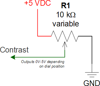
Have a look at this image:

Here you see a typical trimmer used as a voltage divider. Out of circuit (not soldered to the board) there is a fixed 10KΩ (yours is a 2K) resistance between the two end terminals. If you measure the resistance (in Ω) between the two end terminals of your trimmer, you'll always get 2K resistance regardless of the middle terminals positions. This middle terminal, called the wiper, is moved by the screw. For your trimmer you need to measure the resistance between the wiper (middle) and either side terminal. If you measure the resistance between the right term and the wiper with the wiper moved all the way right, you'll get near 0Ω. As you move it left it'll increase to 2K. Same with the middle and left term.
Your trimmer is set up similar to the one above except the voltage is negative. Moving the trimmer from the -5 to ground sets trimmer wiper from -5V to 0V.
Now test your trimmer. It may be fine. You may have a different issue, but it's important to test it properly to confirm it's an issue or not.
If you're measuring between the middle terminal and and outside terminal and it's suck at 2KΩ it's broken.
The trimmer is a variable resistor, it's resistance is measured in ohms (Ω), not frequency.
Have a look at this image:

Here you see a typical trimmer used as a voltage divider. Out of circuit (not soldered to the board) there is a fixed 10KΩ (yours is a 2K) resistance between the two end terminals. If you measure the resistance (in Ω) between the two end terminals of your trimmer, you'll always get 2K resistance regardless of the middle terminals positions. This middle terminal, called the wiper, is moved by the screw. For your trimmer you need to measure the resistance between the wiper (middle) and either side terminal. If you measure the resistance between the right term and the wiper with the wiper moved all the way right, you'll get near 0Ω. As you move it left it'll increase to 2K. Same with the middle and left term.
Your trimmer is set up similar to the one above except the voltage is negative. Moving the trimmer from the -5 to ground sets trimmer wiper from -5V to 0V.
Now test your trimmer. It may be fine. You may have a different issue, but it's important to test it properly to confirm it's an issue or not.
If you're measuring between the middle terminal and and outside terminal and it's suck at 2KΩ it's broken.
Echo North
Well-known member
Do you have the trimmers installed correctly?


Similar threads
- Replies
- 5
- Views
- 552
- Replies
- 2
- Views
- 553


