You are using an out of date browser. It may not display this or other websites correctly.
You should upgrade or use an alternative browser.
You should upgrade or use an alternative browser.
[BUILD] 1176LN Rev D DIY
- Thread starter mnats
- Start date


Help Support GroupDIY Audio Forum:
This site may earn a commission from merchant affiliate
links, including eBay, Amazon, and others.
Echo North
Well-known member
I wouldn't use sockets, just another part that can fail.
The hfe testers in those meters are nothing like the actual circuit . I'd just use the highest ones and move along.
You don't change capacitors for the 5088's, you just install them using the alternate footprint.
The hfe testers in those meters are nothing like the actual circuit . I'd just use the highest ones and move along.
You don't change capacitors for the 5088's, you just install them using the alternate footprint.
Echo North
Well-known member
HMPS said:have you had report of transistors with hfe that low?
the highest one I have is 233, it says not to use less than 250
http://www.groupdiy.com/index.php?topic=34086.0
Read JDBAKKER's post. Your meter is most likely testing hfe with different base current and VCE, so what I get and you get may be different. I might get 350 with my meter and you might get 200 with the same transistor. They maybe are both right, but checking under different conditions. Those 3808's have plenty of gain (hfe).
Mike
dmp said:If you have three resistors in series and one side has -10v and the other has 0v, then you can use ohm's law to see what the voltage should be between the resistor intersections.
I'm building the rev.D: http://mnats.net/files/1176REVD_VOLTS.pdf
so in the revA schematic R74, R75 and R76 are in series and you get -10v on R74 so -10/1000 = .001 amp is the current but since the total is -10v we know that it is 0 v on R75 and R76, right?
so in mine: R79, R67 and R74 are in series and they pass current to the collector of Q13, right? is the collector the middle pin on Q13? So I should check these 3 resistors using ohms law and also
U1 and S2 are passing current to Q13 so I should check those too right?
From the evidence you've posted, it sounds like the GR meter circuit is not correct. You should be able to zero the meter, and there should be positive voltage on the collector of Q13.
The GR amp might have a problem as well, since you said the unit is not compressing signal.


Echo North
Well-known member
It should look the same as in the walk through. You've got something wrong.
Input and Output were printed upside down on my PCB which led to the confusion.
I'm putting 'input +,-' closest to the front of the box
Are the correct resistors for pots as follows for revision d?
Hairball 1176 Revision D Attack Pot 470, .022uf
Hairball 1176 Revision D Release Pot 270k
'posted keywords to help future folks'
I'm putting 'input +,-' closest to the front of the box
Are the correct resistors for pots as follows for revision d?
Hairball 1176 Revision D Attack Pot 470, .022uf
Hairball 1176 Revision D Release Pot 270k
'posted keywords to help future folks'
rokus666
Well-known member
Mike,
What is the HFE value you are getting on your 2n5457 FET's ?
I wanna reference that relative to my multimeter...
What is the HFE value you are getting on your 2n5457 FET's ?
I wanna reference that relative to my multimeter...
Echo North
Well-known member
rokus666 said:Mike,
What is the HFE value you are getting on your 2n5457 FET's ?
I wanna reference that relative to my multimeter...
hFE is a BJT property.
Do not put FETs is your DMM hFE tester.
Mike
john12ax7
Well-known member
What fuse rating are you guys using? My 250mA randomly blew so I put in a 500mA. I measured the peak inrush current turning it off and on several times, typically 100-200mA but it can be as high as 570mA, about 55mA steady state with no input signal.
rokus666
Well-known member
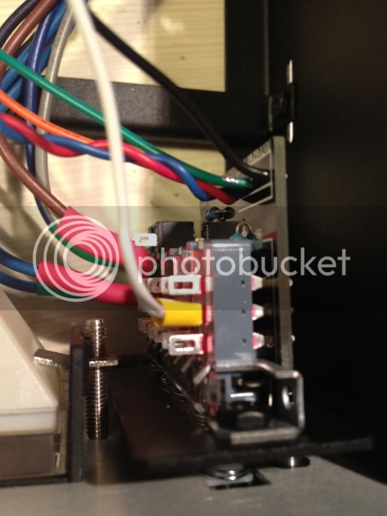
Pin 5 of the GR terminal (white wire) broke off when I put the solder in.
Is it all right if I soldered it on the bottom of the switch(see picture)?
Is it all right if I soldered it on the bottom of the switch(see picture)?
john12ax7
Well-known member
rokus666 said:Pin 5 of the GR terminal (white wire) broke off when I put the solder in.
Is it all right if I soldered it on the bottom of the switch(see picture)?
As long as you do it to the right pin of the switch then yes. I did this on mine as well.
rokus666
Well-known member
Thanks for your help.
I have just powered the unit that I have finished building. It powers ON.
I am letting the unit run for 30 minutes before trying to do anything.
Should I pass the sound through it first before the calibration?
I have noticed only when I press GR button, VU goes all the way up over the top...
Anything unusual?
john12ax7
Well-known member
Either try a test tone with an oscilloscope or some music to see if it's working, then calibrate.
If the GR meter is pinned try adjusting the pot that zeros it to see if you get a change, if not something else is wrong. Actually now that I look at your pic again what is the white wire going to? The center pins on the switch connect to the VU VU on the pcb. The outside pins connect to 28 and 29 on the pcb (though I forget which order, or if it even matters which order). See the pic.
If the GR meter is pinned try adjusting the pot that zeros it to see if you get a change, if not something else is wrong. Actually now that I look at your pic again what is the white wire going to? The center pins on the switch connect to the VU VU on the pcb. The outside pins connect to 28 and 29 on the pcb (though I forget which order, or if it even matters which order). See the pic.
Attachments

radiance
Well-known member
Sorry if I've overlooked this, but is there a explanation on how to wire the bourns input attenuator ??
http://hairballaudio.com/shop/product_info.php?cPath=27&products_id=65
I should have bought the extra pcb with it, I know. Maybe some one has the schematic of this little PCB? Or the layout, so I can figure out the wireing??
http://hairballaudio.com/shop/product_info.php?cPath=27&products_id=65
I should have bought the extra pcb with it, I know. Maybe some one has the schematic of this little PCB? Or the layout, so I can figure out the wireing??
Similar threads
- Replies
- 5
- Views
- 553
- Replies
- 2
- Views
- 553